Serviceguide
Revision History
Server has been stopped
General information
Chapter
System Utilities
Machine Maintenance Procedures
Troubleshooting
FRU Field Replaceable Unit List
Page
Chapter
Features
Page
Page
Features
Storage Subsystem
Graphics
Privacy Control
Power Adapter and Battery
Dimension and Weight
Optical Media Drive
Communication
Special Keys and Controls
Warranty
Ports
Optional Items
Software
Top View Icon Description
Top View Icon Description
Closed Front View Icon Description
Hardware Specifications and Configurations
Left View Icon Description
Right View Icon Description
Base View Icon Description
Function Main Touchpad Left Button Right Button
Touchpad Basics
Lock key Description
Using the Keyboard
Key Description
Windows Keys
Functions supported by Windows XP
Keyboard Hotkeys
Hotkeys
Hot key Icon Function Description
System Block Diagram
10. System Block Diagram
Computer specifications Metric Imperial
Specification Tables
FSB DMI/QBI
CPU
System Memory Specification
Bios
Video Interface Specification
Memory Combinations Slot 1 MB Slot 2 MB Total Memory MB
Keyboard Specification
LAN Interface Specification
RPM
Hard Disk Drive AVL components Specification
8MB
Sata
WD5000BPVT
WD6400BPVT
WD7500BPVT
MK7559GSXP
Super-Multi Drive Specification
DVD-R9, DVD-RAM4.7G
DVD-RW, DVD+RW, DVD-R 4.7G
DVD-ROM
DVD+RW
DVD-RAM DVD+R, DVD+R DL, DVD+R
DVD-R DL, DVD-R 3.95 GB, DVD-R
LCD Inverter not available with this model Specification
LED Specification
LG LP140WH1
LG LP140WH4
Bluetooth Interface Specifications
Graphics Controller Specification
Nvidia ATI
JST
Bluetooth Module Specifications
Mini Card Specification
Camera Specification
3G Card not available in this model
Audio Codec and Amplifier Specification
Wireless Module 802.11b/g/n Specification
Audio Interface Specification
Battery Specification
PCI-E
Hdmi Port Specification
USB Port Specification
AC Adapter Specification
Ehci
Card Reader Specification
System Power Management Specification
Lqfp 48P
System DMA Specification Legacy Mode Power Management
System LED Indicator Specification
System Interrupt Specification Hardware IRQ System Function
Page
CF8 CFB
VGA
PCIDIVO-1
Hardware Specifications and Configurations
System Utilities
Bios Setup Utility
Navigating the Bios Utility
Bios Setup Utility
Information
Bios Information Parameter Description
Uuid
Main
Bios Main Parameter Description Format/Option
Bios Main Parameter Description Format/Option
Security
Bios Security Parameter Description Option
Setting a Password
Changing a Password
Setup Warning Invalid Password
10. Bios Boot
Boot
Exit Parameters Description
Exit
Bios Flash Utilities
DOS Flash Utility
12. Bios Boot
13. DOS Flash Process
15. InsydeFlash
WinFlash Utility
16. Password Error Status
Clearing Bios Passwords
18. Cmos Jumper Description Clear Cmos Jumper
Removing Bios Passwords
Method
Miscellaneous Tools
Using DMITools
22. Asset Tag Menu Item
24. Serial Number Menu Item
26. Veeprom Command Prompt
27. LAN MAC Eeprom LAM MAC Eeprom Parameter Description
Using the LAN MAC Eeprom Utility
28. USB Flash Crisis Disk
Crisis Disk Recovery
System Utilities
System Utilities
Machine Maintenance Procedures
Page
Page
Page
Recommended Equipment
Introduction
Screw List
USB Dimm
Maintenance Flowchart
Wlan RTC
AC Adapter Outlet
Getting Started
Battery Pack Installation
Battery Pack Removal
Dummy Card Removal
Dummy Card Installation
Keyboard Latches
Keyboard Removal
Keyboard Installation
ODD Module in Lower Cover
ODD Optical Disk Drive Module Removal
Size Quantity Screw Type
ODD Module Installation
Lower Cover Screw Location
Lower Cover Removal
10. Lower Cover Removal
Lower Cover Installation
11. Component Location
Dimm Dual In-line Memory Module Module Removal
Dimm Module Installation
13. Wlan Module
Wlan Wireless Local Area Network Module Removal
M2.5*4.0
Wlan Module Installation
USB Module Removal
USB Module Installation
M2.5*3.0
RTC Battery Installation
RTC Battery Removal
17. Bluetooth Module
Bluetooth Module Removal
19. Bluetooth Module
Bluetooth Module Installation
20. Thermal Module
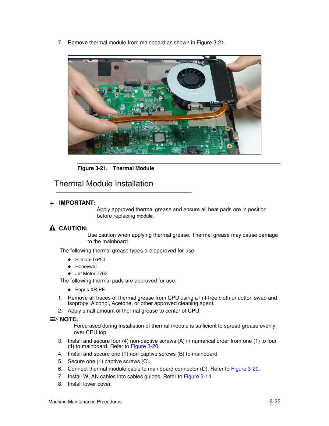
Thermal Module Removal
21. Thermal Module
Thermal Module Installation
M2.5*3.0 Ni
22. HDD Module Location
HDD Hard Disk Drive Module Removal
24. HDD Module
HDD Module Installation
25. Mainboard Location
Mainboard Removal
26. Mainboard
Mainboard Installation
27. LCD Hinge Screws
LCD Liquid Crystal Display Module Removal
LCD Module Installation
29. Speaker
Speaker Removal
Speaker Installation
31. LCD Bezel
LCD Bezel Removal
Size Quantity Screw Type M2.5*4.0
LCD Bezel Installation
34. Camera Module Location
Camera Module Removal
Camera Module Installation
36. LCD Panel
LCD Panel Removal
LCD Panel Installation
LCD Bracket Removal
LCD Bracket Installation
M2.0*3.0
39. Lvds Cable
Lvds Cable Removal
41. Lvds Cable
Lvds Cable Installation
Wlan Antenna Removal
Wlan Antenna Installation
Troubleshooting
Introduction -3 General Information
Common Problems
Power On Issue
Power On Issues
No Display Issue
No Display Issues
Abnormal Video
LCD Failure
LCD Failure
Keyboard Failure
Keyboard Failure
Touchpad Failure
Touchpad Failure
Internal Speaker Failure
Internal Speaker Failure
Troubleshooting
Microphone Failure
Microphone Failure
USB Failure
USB Failure
Other Functions Failure
Undetermined Problems
Intermittent Problems
Post Codes
Post Code Range Phase
Peimemoryinstall PEI
Peicpuhtreset PEI
Peiswitchstack PEI
Peienterrecoverymode PEI
DXECF9RESET
Peirecoverystartflash PEI
Dxesmmaccess DXE
Dxesmarttimerinit DXE
Bdsbeforepciioinstall BDS
Bdsinstallhotkey BDS
Dxerelocatesmbase DXE
Dxefirstsmi DXE
Bdsendofbootselection BDS
Bdsenumerateallbootoption BDS
Bdsentersetup BDS
Bdsenterbootmanager BDS
S3INSTALLS3MEMORY PEI
S3RESTOREMEMORYCONTROLLER PEI
S3SWITCHSTACK PEI
S3BEFOREACPIBOOTSCRIPT PEI
10. InsydeH2ODDT Debugger Post Code Table
Jumper and Connector Locations
Page
Mainboard Top Description
Mainboard Jumper and Connector Locations
Mainboard Bottom Description
Clearing Password Check
Clearing Password Check and Bios Recovery
Clear Cmos Jumper
Bios Recovery by Crisis Disk
Steps for Bios Recovery from USB Storage
Jumper and Connector Locations
FRU Field Replaceable Unit List
Exploded Diagrams FRU List Screw List
FRU Field Replaceable Unit List
Exploded Diagrams
FRU Field Replaceable Unit List
LCD Assembly Exploded Diagram
FRU List
Battery
FRU List Category Description Acer Part No
Adapter
Cable
Board
CASE/COVER/BRACKET Assembly
DVD/RW Super Multi Sata Module
DVD RW Drive
ODD Bezel Super Multi
ODD Bracket
Sata 8MB LF F/W0001SDM1
LF F/WGJ001J
BS,MK3265GSX Sata 8MB LF F/WGJ001J
WD6400BEVT-22A0RT0, ML320 Sata 8MB LF
WD5000BEVT-22A0RT0, ML320M,WD Sata
LF F/WGJ002J
WD6400BPVT-22HXZT1, ML375M Sata 8MB
Keyboard
LCD Module 14 LED Glare IMR W/CCD
LCD
ANTENNA*2 Black
LCD Cover W/ ANT IMR Black
LCD Bracket W/ Hinge L
LCD Bezel for CCD
LCD Bracket W/ Hinge R
LCD Cable
LCD Cover W/ ANT IMR RED
ANTENNA*2 RED
Main Board UMA E350 1.6G, W/CARD
Mainboard
READER,MIC Main Board Seymourxt E350 1.6G
Card READER,MIC
Thermal Module UMA 18W
Heatsink
Thermal Module DIS 18W
Speaker
Miscellaneous
Screw List
Model Definition and Configuration
Acer 4255 -1Aspire 4253G
RO, Description Model Country Acer Part No
Acer
AAP
W7ST32EMASID1 MC
W7HB64SCASCN1 MC
China
W7HB64EMASID1 MC
W7ST32EMASEA1 MC
W7HB64EMASEA1 MC
W7ST32EMASTH1 MC
W7ST32EMASTH4 MC
W7ST32EMASTH3 MC
W7HP64EMASEA1 MC
CPU LCD
CPU, LCD Model Country Acer Part No
AMDE350B NLED14WXGAG
AS4253-E35 ACLA-Spanish LX.RDT0C.001
UMA
VGA Chip, Vram Model Country Acer Part No
AS4253-E35 Thailand LX.RDU0C.005
AS4253-E35 China LX.RDT0C.011
HDD 1GB
Memory 1, Memory 2, HDD Model Country Acer Part No
SO1GBIII10
SO2GBIII10
SO2GBIII10 SO1GBIII10
ODD
ODD, Extra SW1, Card Reader Model Country Acer Part No
Extra SW1 Card Reader
NSM8XS
AS4253-E35 ACLA-Spanish LX.RDT01.001
AMD A50M
LAN1
BGN FCH
AS4253-E35 Indonesia LX.RDT08.002 3rd WiFi
AS4253-E35 Malaysia LX.RDT0C.012 3rd WiFi
Battery, Adapter, Camera Model Country Acer Part No
Battery, Adapter, Camera Model Country Acer Part No
Battery, Adapter, Camera Model Country Acer Part No
LINPUSATH3
Aspire 4253G
LINPUSATH1
LINPUSATH4
Thailand LX.RDW08.003 AS4253G-E352G50Mnkk EM
LINPUSAPH1
Seymourxt
10. VGA Chip, Vram Model Country Acer Part No
11. Memory 1, Memory 2, HDD Model Country Acer Part No
AS4253G-E3 Thailand LX.RDX0C.001
12. ODD, Extra SW1, Card Reader Model Country Acer Part No
AS4253G-E3 Philippines LX.RDW0C.004
14. Battery, Adapter, Camera Model Country Acer Part No
14. Battery, Adapter, Camera Model Country Acer Part No
Model Definition and Configuration
Test Compatible Components
Microsoft Windows 7 Environment Test
Test Compatible Components
Audio Codec
Microsoft Windows 7 Environment Test
Card Reader
Camera
HDD
375G/P Sata 8MB LF
LF+HF F/WGN003J
LAN
Keyboard
Memory
NB Chipset
Software
SB Chipset
VGA Chip
Wireless LAN
WiFi Antenna
Pifa
LITE-ON BGN
Online Support Information
Introduction
Online Support Information
Online Support Information