Aspire 5252/5552/5552G Series Service Guide
Revision History
III
Copyright
Page
Conventions
Preface
Table of Contents
Table of Contents
Microsoft Windows 7 Environment Test
Troubleshooting 149
Table of Contents
Chapter
Features
Audio
Graphics
Storage
Aspire 5252/5552
Power Subsystem
Dimensions and Weight
Optical Media Drive
Communication
Software
Special Keys and Controls
Interface
Environment
Warranty
Optional Items
Discrete Model
System Block Diagram
ATI SB820M
UMA Model
Front View
Your Acer Notebook tour
Icon Description
HDD
Left View
Rear View
Hdmi
Right View
Icon Function Description
Indicators
Base View
Function Left Button Right Button Main Touchpad
Touchpad Basics
Lock key Description
Using the Keyboard
Lock Keys and embedded numeric keypad
Key Description
Windows Keys
Hotkey Icon Function Description
Hot Keys
CPU
Hardware Specifications and Configurations
UMA
Southbridge Specification
Northbridge Specification
AMD RS880M
AMD SB820M
2MB
Bios
LAN Interface Specification
System Memory Specification
Ddriii SO-DIMM
Memory Combinations Slot Total Memory
Bluetooth Interface Specification
Wireless Module 802.11b/g/n Specification
BD Drive Interface Specification
Super-Multi Drive Interface Specification
DVD-R 3.9GB, 4.7GB DVD-R DL, DVD-RW, DVD-RAM, DVD+R, DVD+R
Hlds BD Combo Drive Tray DL 4X CT10 LF, Panasonic BD Combo
Graphics Controller Specification Discrete
Audio Subsystem Specification
Video Interface Specification
Specification Discrete
Hdmi Port Specification
USB Port Specification
Pcmcia Port Not available in this model Specification
System Board Major Chips Specification Discrete
Battery Specification
Keyboard Specification
Ports Specification
Ccfl Specification
LED Specification
Samsung LTN156AT02-A04
Samsung LTN156AT01-A01
Graphic Driver Supported Resolution Bits
LCD Inverter Specification
Camera Specification
AC Adapter Specification
Power Specification Legacy Acpi Mode Power Management
Card Reader Specification Discrete
System LED Indicator Specification
Chapter
Navigating the Bios Utility
Bios Setup Utility
Information
Aspire AS5552/AS5552G Bios
Parameter Description
Uuid
Parameter Description Format/Option
Disabled
Main
Security
Disabled or
Parameter Description Option
Clear or Set
Removing a Password
Setting a Password
Continue
Changing a Password
USB CD/DVD ROM
Boot
Exit
Information Main Security Boot Exit Exit Saving Changes
Bios Flash Utilities
USB HDD
DOS Flash Utility
USB FDD
Page
WinFlash Utility
Remove HDD Password
Remove HDD/BIOS Password Utilities
Password
UnlockHD
Cleaning Bios Passwords
Removing Bios Passwords
Using Boot Sequence Selector
Output
Using DMITools
Input
Disassembly Requirements
Machine Disassembly and Replacement
Pre-disassembly Instructions
Main Screw List Quantity Part Number
Disassembly Process
Screw List Step Quantity
External Module Disassembly Process
External Modules Disassembly Flowchart
Removing the Battery Pack
Removing the SD Dummy Card
Removing the Keyboard
Chapter
Step Size Quantity Screw Type ODD Module M2.5*8
Removing the ODD Module
Step Size Quantity Screw Type ODD Bracket M2*3
Step Size Quantity Screw Type
Removing the Logic Lower Door
Step Size Quantity Screw Type 3G Cover M2.5*8
Removing the 3G Cover Discrete Only
Removing the Dimm Module
Step Size Quantity Screw Type Wlan Module M2*3
Removing the Wlan Module
Detach the Wlan module from the Wlan socket Chapter
Removing the HDD Module
Step Size Quantity Screw Type HDD Carrier M3*3
Removing the RTC Battery UMA Only
Main Unit Disassembly Flowchart
Main Unit Disassembly Process
Removing the Upper Cover
Page
Chapter
Step Size Quantity Screw Type Upper Cover M2.5*5
Removing the Speaker Module
Step Size Quantity Screw Type Power Board M2*3
Removing the Power Board
Removing the Touchpad FFC
Removing the Card Reader Board Discrete Only
Remove one 1 screw from the card reader board
Removing the USB Board
Step Size Quantity Screw Type USB Board M2*3
Removing the Bluetooth Module
Lift the Bluetooth cable from the cable guides
Removing the ODD Connector Board UMA Only
Removing the Mainboard
UMA
Chapter
Page
Removing the Thermal Module
Carefully lift the thermal module clear of the mainboard
Removing the CPU
Removing the LCD Assembly
Step Size Quantity Screw Type LCD Assembly M2.5*8
Remove the LCD assembly from the lower cover Chapter
Removing the DC-IN Assembly
LCD Module Disassembly Flowchart
LCD Module Disassembly Process
Step Size Quantity Screw Type LCD Bezel M2.5*6
Removing the LCD Bezel
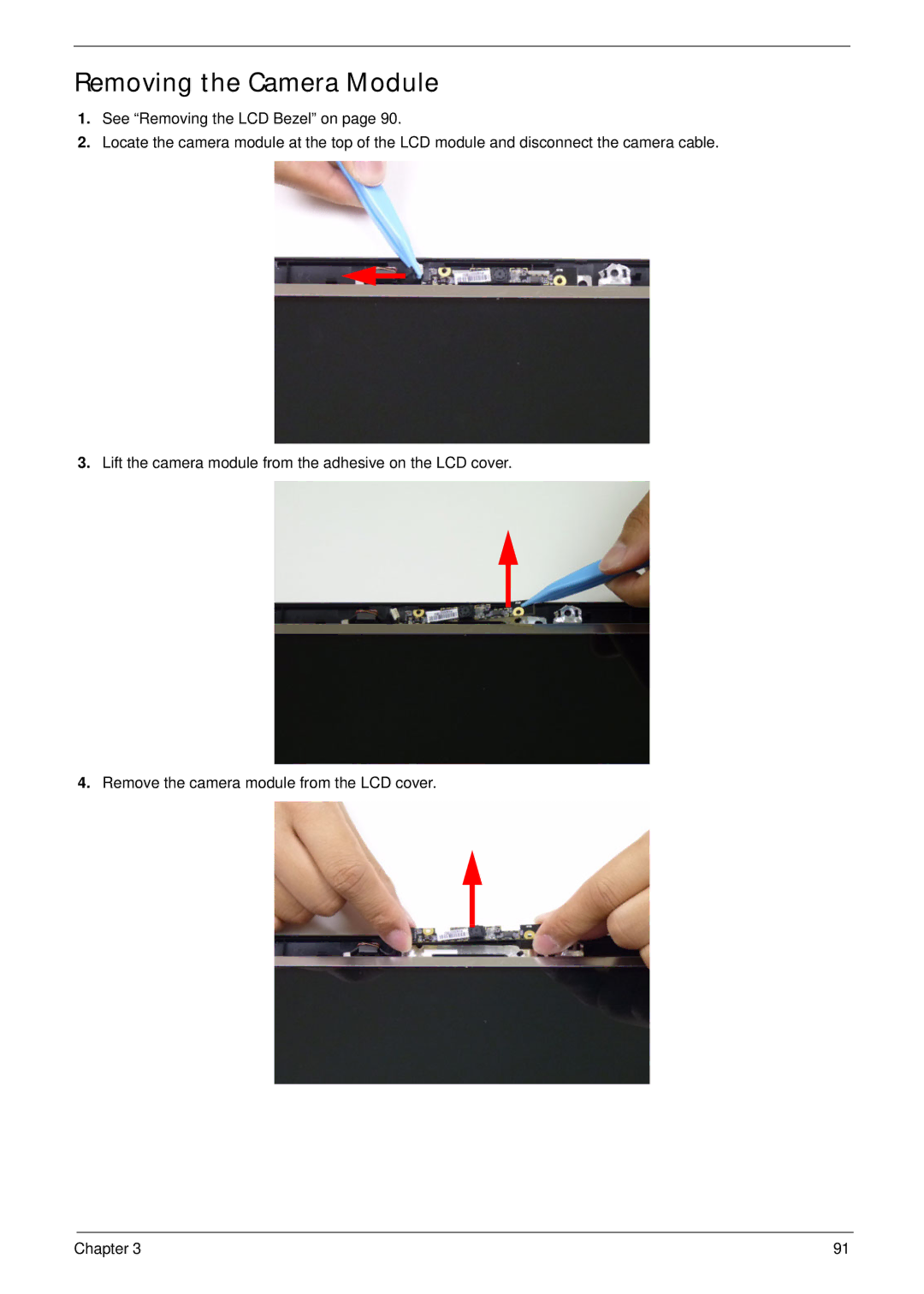
Removing the Camera Module
Step Size Quantity Screw Type Inverter Board M2.5*5
Removing the Inverter Board LCD Only
Page
Step Size Quantity Screw Type LCD/LED Panel M2.5*5
Removing the LCD/LED Panel
Step Size Quantity Screw Type LCD Brackets M2*3
Removing the LCD Brackets
LCD LED
Removing the Lvds cable
Removing the Microphone Cable
Lift the microphone set clear of the panel
Removing the Antennas
100 Chapter
Replacing the Antennas
LCD Module Reassembly Procedure
102 Chapter
Replacing the Microphone Cable
104 Chapter
Replacing the Lvds Cable
Replacing the LCD Brackets
Replacing the LCD/LED Panel
Replacing the Inverter Board LCD Only
Page
Replacing the Camera Module
Replacing the LCD Bezel
Replacing the DC-IN Assembly
Main Module Reassembly Procedure
Replacing the LCD Assembly
114 Chapter
Page
Replacing the CPU
Mastro B6
Replacing the Thermal Module
118 Chapter
Chapter 119
Replacing the Mainboard
UMA
122 Chapter
Replacing the ODD Connector Board UMA Only
Replacing the Bluetooth Board
Replacing the USB Board
126 Chapter
Replacing the Card Reader Board Discrete Only
128 Chapter
Replacing the Touchpad FFC
Replacing the Power Board
Replacing the Speaker Module
Replacing the Upper Cover
Page
134 Chapter
Step Size Quantity Screw Type Upper Cover M2.5*5
Replacing the RTC Battery UMA Only
Replacing the HDD Module
138 Chapter
Replacing the Wlan Module
Replacing the Dimm Modules
Replacing the 3G Cover Discrete Only
Replacing the Lower Logic Door
Replacing the ODD Module
144 Chapter
Replacing the Keyboard
Replacing the SD Dummy Card
Replacing the Battery
148 Chapter
Symptoms Verified Go To
Common Problems
Computer Shutsdown Intermittently
Power On Issue
No Post or Video
No Display Issue
Abnormal Video Display
Random Loss of Bios Settings
Built-In Keyboard Failure
LCD Failure
Internal Speaker Failure
Touchpad Failure
Select Set up microphone
Sound Problems
Microphone Problems
Select Startup Repair
HDD Not Operating Correctly
Select Repair your computer
ODD Not Operating Correctly
ODD Failure
Discs Do Not Play
Drive Not Detected
Thermal Unit Failure
Wireless Function Failure
Other Failures
External Mouse Failure
Dimm
Intermittent Problems
Undetermined Problems
Post Codes
Post Code Range Phase
Peirecoverymediafound PEI
Peienterrecoverymode PEI
Peirecoverymedianotfound PEI
Peirecoveryloadfiledone PEI
Bdsendofbootselection BDS
Bdsenumerateallbootoption BDS
Bdsentersetup BDS
Bdsenterbootmanager BDS
Smmacpienableend SMM
Smmacpienablestart SMM
Smmacpidisablestart SMM
Smmacpidisableend SMM
Top View Discrete
Bottom View Discrete
Top View UMA
JRJ45
Bottom View UMA
LED6 SW2 LED7 Wwan LED SW3 LED8
Power BoardDiscrete
Power BoardUMA
USB Board
USB Connector
Card Reader Board Discrete only
JUSB1/JUSB2
Clearing Password Check
Clearing Password Check and Bios Recovery
Steps for Clearing Bios Password Check
Clear Cmos Jumper
Bios Recovery Boot Block
Bios Recovery by Crisis Disk
Bios Recovery Hotkey
Steps for Bios Recovery from USB Storage
176 Chapter
FRU Field Replaceable Unit List
Description Acer Part No
Aspire AS5552/AS5552G Exploded Diagrams
Main Assembly
Upper Assembly
LCD Assembly
LED Assembly
Aspire AS5552/AS5552G FRU List
Battery
Category Description Acer Part No
Adapter
Cable
CASE/COVER/BRACKET Assembly
HDD/HARD Disk Drive
CPU/PROCESSOR
Keyboard
22A0RT0, ML320M,WD Sata 8MB LF F
DVD RW Drive
BD Combo Drive
LCD
Cost Ccfl LCD Samsung 15.6W Wxga Glare
Ccfl LCD CMO 15.6W Wxga Glare
Ccfl LCD LPL 15.6W Wxga Glare
ANTENNA*2, CCD 1.3M, Silver LCD Cover IMR-SILVER
ANTENNA*2, CCD 1.3M, Brown LCD Cover IMR-BROWN
ANTENNA*2, CCD 1.3M, RED LCD Cover IMR-RED
ANTENNA*2, CCD 1.3M, Black LED Cover IMR-BLACK
Assy LED Module 15.6W Wxga Glare W
LED Bracket R&L
LED Cable for W/CMOS
LED LCD Samsung 15.6W Wxga Glare
LED LCD BOE 15.6W Wxga Glare
ANTENNA*2, CCD 1.3M, Brown LED Cover IMR-BROWN
ANTENNA*2, CCD 1.3M, RED LED Cover IMR-RED
Mainboard AS5552 AMD RS880M LF
Mainboard
Heatsink
Memory
Miscellaneous
Speaker
Screw
Screw List
Model Country Acer Part No Description
Appendix a
AS5252
Appendix a
Appendix a 202
Model Country Acer Part No Description
Appendix a 204
AAP
CPU LCD VGA
Model Country
Memory
Chip
AMDV140 NLED15.6WXGAG UMA SO2GBIII10
Appendix a 208
Turkey AAP340
Appendix a 210
Extra SW1
Model Country Memory
HDD 1GB ODD
Appendix a 212
AS5552 ACLA-Spain N320GB5.4KS
Appendix a 214
Model Country Card Reader Wireless LAN1 Bluetooth
Appendix a 216
Italy In-1 card reader 3rd WiFi 2x2 BGN N854G50Mnkk AS5552
Appendix a 218
Belgium In-1 card reader 3rd WiFi 2x2 BGN P343G32Mnkk AS5552
W7HB64SCASCN1 MC
AS5552G
W7HB64RUASRU1 MC
Appendix a 222
China LX.R4A01.001 AS5552G-N852G32Mnrr
Appendix a 224
Model Country Acer Part No Description
VGA Chip
CPU LCD
NLED15.6WX Madisonpro 1G-DDR3
Appendix a 228
Denmark APN950
Model Country Memory HDD 1 GB
P543G32Mnkk AS5552G
Appendix a 232
N953G32Mnkk AS5552G
LAN1
Model Country Extra SW1 Card Reader Wireless Bluetooth
Turkey McAfee In-1 card 3rd WiFi P543G32Mnkk Reader
Appendix a 236
France McAfee In-1 card 3rd WiFi N854G50Mnkk Reader
Appendix a 238
Appendix B
Test Compatible Components
Microsoft Windows 7 Environment Test
Battery
Brand Type Description Acer Part No Adapter
Audio Codec
HDD
Brand Type Description Acer Part No
LAN
Keyboard
MEM
NB Chipset
Wireless LAN
WiFi Antenna
SB Chipset
Software
244
Appendix C
Online Support Information
246
Index
248
Removing 58, 62
250