Pre-disassembly Instructions
Before proceeding with the disassembly procedure, make sure that you do the following:
1.Turn off the power to the system and all peripherals.
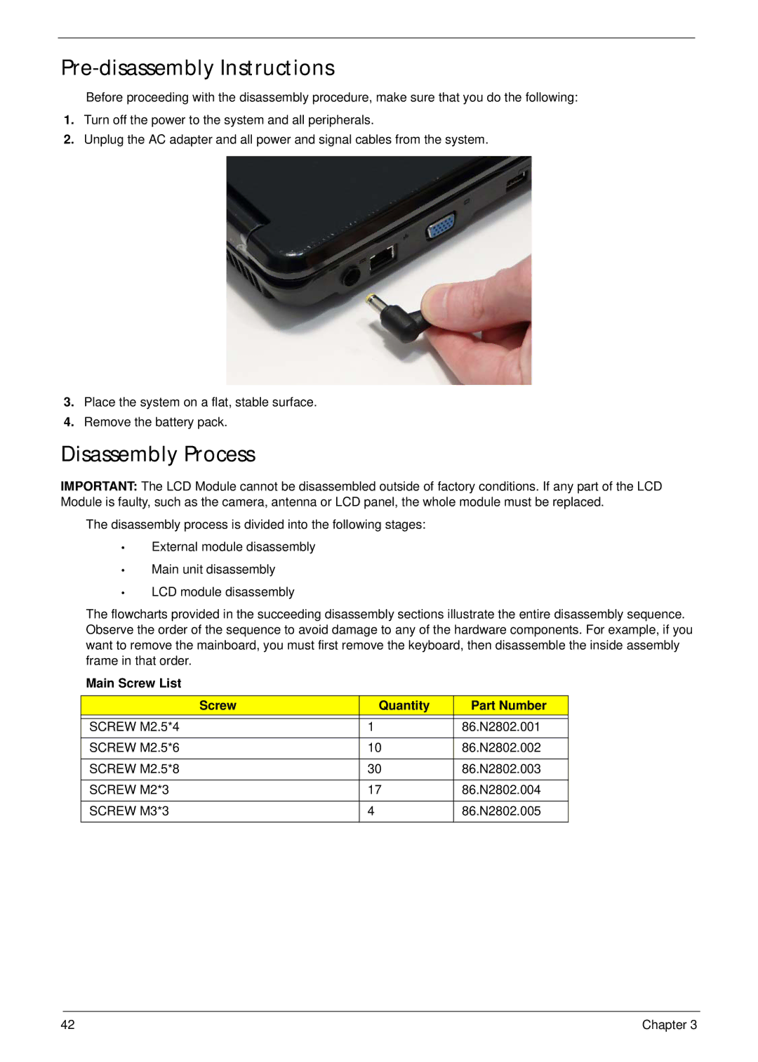
2.Unplug the AC adapter and all power and signal cables from the system.
3.Place the system on a flat, stable surface.
4.Remove the battery pack.
Disassembly Process
IMPORTANT: The LCD Module cannot be disassembled outside of factory conditions. If any part of the LCD Module is faulty, such as the camera, antenna or LCD panel, the whole module must be replaced.
The disassembly process is divided into the following stages:
•External module disassembly
•Main unit disassembly
•LCD module disassembly
The flowcharts provided in the succeeding disassembly sections illustrate the entire disassembly sequence. Observe the order of the sequence to avoid damage to any of the hardware components. For example, if you want to remove the mainboard, you must first remove the keyboard, then disassemble the inside assembly frame in that order.
Main Screw List
Screw | Quantity | Part Number |
|
|
|
SCREW M2.5*4 | 1 | 86.N2802.001 |
|
|
|
SCREW M2.5*6 | 10 | 86.N2802.002 |
|
|
|
SCREW M2.5*8 | 30 | 86.N2802.003 |
|
|
|
SCREW M2*3 | 17 | 86.N2802.004 |
|
|
|
SCREW M3*3 | 4 | 86.N2802.005 |
|
|
|
42 | Chapter 3 |