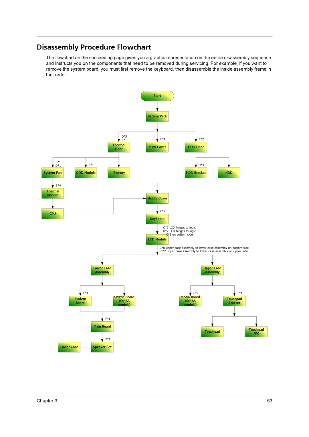
Disassembly Procedure Flowchart
The flowchart on the succeeding page gives you a graphic representation on the entire disassembly sequence and instructs you on the components that need to be removed during servicing. For example, if you want to remove the system board, you must first remove the keyboard, then disassemble the inside assembly frame in that order.
Start |
Battery Pack |
D*5
F*1
Thermal |
Door |
F*1F*2
Mimi Cover | HDD Door |
B*1
D*1
System Fan |
B*4
Thermal |
Module |
CPU |
F*1
ODD Module |
Memory |
H*4
HDD Bracket | HDD |
Middle Cover |
F*2
Keyboard |
C*2 LCD hinges to logic |
D*2 LCD hinges to logic |
C*2 on bottom side |
LCD Module |
C*8 upper case assembly to lower case assembly on bottom side C*2 upper case assembly to lower case assembly on upper side
Lower Case |
Assembly |
F*1
Modem | Switch Board | |
(for AS | ||
Board | ||
models) | ||
|
F*1
Main Board |
F*2
Lower Case | Speaker Set |
Upper Case |
Assembly |
F*2 | F*1 | |
Media Board | Touchpad | |
(for AS | ||
Bracket | ||
models) | ||
|
Touchpad | Touchpad | |
FFC | ||
|
Chapter 3 | 53 |