Aspire 5742/5742G/5742Z/5742ZG Series Service Guide
Revision History
Copyright
III
Conventions
Preface
Page
Table of Contents
Viii
Aspire 5742/5742G
Aspire 5742Z/5742ZG
Table of Contents
Features
Chapter
Optical Media Drive
Graphics
Storage
Webcam
Privacy control
Wireless and networking
Power adapter and battery
Wlan
Input and control
Dimensions and weight
Warranty
Input and output
Software
System Block Diagram
UMA
Discrete nVidia
Discrete ATI
Your Acer Notebook tour
Top View
Icon Description
Battery bay Houses the computers battery pack
Rear view
Left View
Right View
Base view
Indicators
Icon Function Description
HDD
Touch Pad Basics
Function Left Button Right Button Main TouchPad
Using the Keyboard
Lock Keys and embedded numeric keypad
Lock key Description
Windows Keys
Key Description
Hot Keys
Hotkey Icon Function Description
Hardware Specifications and Configurations
CPU
System Memory Specification
512MB,1GB,2GB,4GB DDR3 RAM
Memory Combinations Slot Total Memory
Bios
LAN Interface Specification
0MB
Keyboard Specification
Hard Disk Drive Interface Specification
Bluetooth Interface Specification
Audio Interface Specification
LED Specification
Camera Specification
LCD Inverter not available with this model Specification
LCD Display Supported Resolution Bits Intel
3G Module not available with this model Specification
Audio Codec and Amplifier Specification
Wireless Module 802.11b/g/n Specification
Battery Specification
Vram Nvidia
Vram ATI
AC Adapter UMA Specification
System Board Major Chips Specification
Ports Specification
AC Adapter nVidia Specification
AC Adapter ATI Specification
System Power Management Legacy Specification Mode
Card Reader UMA & Discrete Specification
System LED Indicator Specification
Chapter
Bios Setup Utility
Navigating the Bios Utility
Parameter Description
Aspire 5742/5742G/5742Z/5742ZG Bios
Information
Uuid
Disabled
Main
Parameter Description Format/Option
Parameter Description Option
Disabled or
Security
Clear or Set
Setting a Password
Removing a Password
Changing a Password
Continue
Boot
IDE1 HL-DT-STDVDRAM GT32N
Exit
Exit Exit Saving Changes
Bios Flash Utilities
DOS Flash Utility
Stdvdram GT32N
WinFlash Utility
Password
Remove HDD/BIOS Password Utilities
Remove HDD Password
UnlockHD
Removing Bios Passwords
Cleaning Bios Passwords
Using Boot Sequence Selector
Using DMITools
Input
Output
Chapter
Machine Disassembly and Replacement
Disassembly Requirements
Pre-disassembly Instructions
Screw 2.5D
Disassembly Process
Main Screw List Quantity Part Number
Screw 3.0D
External Module Disassembly Process
External Modules Disassembly Flowchart
Screw List Step Quantity
Removing the Battery Pack
Removing the SD Dummy Card
Removing the ODD Module
Step Size Quantity Screw Type ODD Module M2.5*8
Step Size Quantity Screw Type ODD Bracket M2*3
Removing the Logic Lower Door
Step Size Quantity Screw Type Logic lower door M2.5*8
Removing the 3G Cover Discrete Only
Step Size Quantity Screw Type 3G Cover M2.5*8
Removing the RTC Battery UMA Only
Remove the RTC battery from the lower cover as shown
Removing the Dimm Module
Removing the Wlan Module
Step Size Quantity Screw Type Wlan Module M2*3
Detach the Wlan module from the Wlan socket Chapter
Removing the HDD module Module
Step Size Quantity Screw Type HDD Carrier M3*3
Removing the Keyboard
Page
Screw Assy
Main Unit Disassembly Process
Main Unit Disassembly Flowchart
CPU Thermal
Removing the Upper Cover
Step Size Quantity Screw Type
Chapter
Page
Step Size Quantity Screw Type Upper Cover M2.5*5
Page
Removing the Speaker Module
Lift the speaker module clear of the device Chapter
Removing the Power Board
Step Size Quantity Screw Type Power board M2*3
Removing the Touch Pad FFC
Page
Removing the Card Reader Module Discrete Only
Step Size Quantity Screw Type Card Reader M2*3
Removing the USB Board
USB
Removing the Bluetooth Board
Discrete
UMA
Disconnect the Bluetooth cable from the connector as shown
Removing the ODD Connector Board UMA Only
Removing the Mainboard
Step Size Quantity Screw Type Mainboard M2.5*5
Page
Chapter
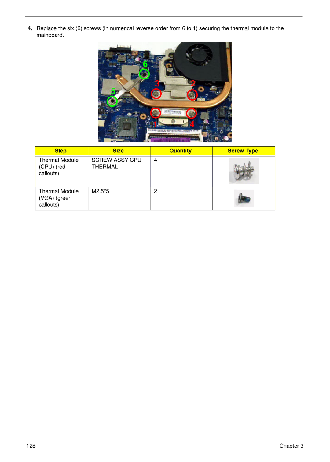
Removing the Thermal Module
Screw Assy CPU
Thermal
Removing the CPU
Removing the LCD Module
See Removing the Mainboard on
Page
UMA
Step Size Quantity Screw Type LCD Module M2.5*5
Removing the DC-In Assembly
LCD Module Disassembly Process
LCD Module Disassembly Flowchart
Removing the LCD Bezel
Step Size Quantity Screw Type LCD Bezel M2.5*6
Remove the bezel from the LCD module Chapter
Removing the CCD Module
Removing the Inverter Module LCD Only
Step Size Quantity Screw Type Inverter Module M2.5*5
102 Chapter
Page
Removing the LCD/LED Panel
Step Size Quantity Screw Type LCD Brackets M2.5*5
Page
Removing the LCD Brackets
Step Size Quantity Screw Type LCD Brackets M2*3
Removing the Lvds Cable
LCD LED
Removing the Microphone Cable
Lift the microphone set clear of the panel Chapter 109
Removing the Antennas
LCD Module Reassembly Procedure
Replacing the Antennas
Replacing the Microphone Cable
Page
Replacing the Lvds Cable
Replacing the LCD Brackets
Replacing the LCD/LED Panel
Replacing the Inverter Board
118 Chapter
Replacing the CCD Module
Replacing the LCD Bezel
Main Module Assembly Procedure
Replacing the DC-In Assembly
Replacing the LCD Module
Place the black antenna cable into the cable guides
124 Chapter
Replacing the CPU
126 Chapter
Replacing the Thermal Module
Mastro B6
VGA/RAM PAD
Callouts Thermal Module M2.5*5 VGA green
Replacing the Mainboard
130 Chapter
Step Size Quantity Screw Type Mainboard M2.5*5
Connect the Lvds cable to the mainboard
Replacing the ODD Connector Board UMA Only
Replacing the Bluetooth Board
Replacing the USB Board
Step Size Quantity Screw Type USB Board M2*3
136 Chapter
Replacing the Card Reader Board Discrete Only
138 Chapter
Replacing the Touchpad FFC
Replacing the Power Board
Replacing the Speaker Module
Replacing the Upper Cover
Page
144 Chapter
Step Size Quantity Screw Type Upper Cover M2.5*5
Replacing the RTC Battery UMA Only
Replacing the HDD Module
148 Chapter
Replacing the Wlan Module
Connect the two 2 antenna cables to the module
Replacing the Dimm Modules
Replacing the 3G Cover Discrete Only
Replacing the Lower Logic Door
Replacing the ODD Module
Chapter 155
Replacing the Keyboard
Replacing the SD Dummy Card
Replacing the Battery
Common Problems
Symptoms Verified Go To
Power On Issue
Computer Shutsdown Intermittently
No Display Issue
No Post or Video
Random Loss of Bios Settings
Abnormal Video Display
LCD Failure
Internal Keyboard Failure
Touch Pad Failure
Internal Speaker Failure
Sound Problems
Microphone Problems
Select Set up microphone
Microphone Record Failure
USB Failure Right side
HDD Not Operating Correctly
Select Repair your computer
Select Startup Repair
ODD Failure
ODD Not Operating Correctly
Discs Do Not Play
Drive Not Detected
Wireless Function Failure
Bluetooth Function Test Failure
1 card Function Test Failure
Thermal Unit Failure
External Mouse Failure
Cosmetic Failure
Other Failures
Intermittent Problems
Undetermined Problems
Dimm
Post Code Range Phase
Post Codes
Peienterrecoverymode PEI
Peimemoryinstall PEI
Peiswitchstack PEI
Peirecoverymediafound PEI
Bdsbeforepciioinstall BDS
Dxesmarttimerinit DXE
Bdsinstallhotkey BDS
Dxemtcinit DXE
Bdsentersetup BDS
Bdsenumerateallbootoption BDS
Bdsendofbootselection BDS
Bdsenterbootmanager BDS
Functionality Name Include\ PostCode.h Phase Description
Smmacpidisablestart SMM
Smmacpienablestart SMM
Smmacpienableend SMM
Smmacpidisableend SMM
SW1/SW2
JTP1
JUSB2
JMIC2
LED2
Discrete nVidia
FFC
SW2/SW3
JKB1
Discrete ATI
JSPK2
JP1
Bottom View
Connect to Wlan
USB connector U34
USB Connector
USB/B Board
Description
PEW71/91 Wlan LED
Power Board
PEW71/91 ON/OFF LED
PEW71/91 Media LED SW1
PEW71/91 Media LED
PEW51 Wlan LED
PEW51 Media LED SW1
PEW71/91 ON/OFF LED LED10 PEW71/91 Wlan LED
PEW71/81/91 Media LED LED11
PEW51 Media LED LED12 PEW51 Wlan LED SW1
CR/B Board
JREAD1
JREAD2
ODD connector
ODD Board
JODD2
Steps for Clearing Bios Password Check
Clearing Password Check and Bios Recovery
Clearing Password Check
Clear Cmos Jumper
R671/R675 Clear Cmos Jumper
Bios Recovery Hotkey
Bios Recovery by Crisis Disk
Bios Recovery Boot Block
Steps for Bios Recovery from USB Storage
198 Chapter
FRU Field Replaceable Unit List
Aspire Exploded Diagrams
Main Assembly
Description Acer P/N
Discrete
Uniload DOOR-DIS
Lower Cover
Uniload DOOR-UMA
3G DOOR-DIS
LCD Assembly
LED Assembly
Category Description
Battery
Aspire FRU List
Adapter
Cable
CASE/COVER/BRACKET Assembly
CPU/PROCESSOR
PCB Sata 8MB LF F/W0001SDM1
HDD/HARD Disk Drive
Sata 8MB LF F/W0001SDM1
22ZEST0, ML320S, 4K Drive Sata 8MB LF F/W
Keyboard
BD Combo Drive
DVD RW Drive
LCD
Antenna WLAN-MAIN
LCD Cover IMR-BLACK
LCD Bezel for W/CMOS
Antenna WLAN-AUX
ANTENNA*2, CCD 1.3M, Brown LCD Cover IMR-BROWN
ANTENNA*2, CCD 1.3M, RED LCD Cover IMR-RED
Assy LED Module 15.6W Wxga Glare W
ANTENNA*2, CCD 1.3M, Black LED Cover IMR-BLACK
LED LCD Samsung 15.6W Wxga Glare
LED Cable for W/CMOS
LED Bracket R&L
LED LCD BOE 15.6W Wxga Glare HT156WXB
ANTENNA*2, CCD 1.3M, Brown LED Cover IMR-BROWN
ANTENNA*2, CCD 1.3M, RED LED Cover IMR-RED
ANTENNA*2, W/O CCD, Black LCD Cover IMR-BLACK
LCD Bezel for W/O Cmos
LCD Cable for W/O Cmos
ANTENNA*2, W/O CCD, Silver LCD Cover IMR-SILVER
ANTENNA*2, W/O CCD, Brown LCD Cover IMR-BROWN
ANTENNA*2, W/O CCD, RED LCD Cover IMR-RED
ANTENNA*2, W/O CCD, Black LED Cover IMR-BLACK
LED Cable for W/O Cmos
ANTENNA*2, W/O CCD, Silver LED Cover IMR-SILVER
ANTENNA*2, W/O CCD, Brown LED Cover IMR-BROWN
ANTENNA*2, W/O CCD, RED LED Cover IMR-RED
Mainboard
Memory
Heatsink
Speaker
Miscellaneous
Acer Description
Screw List
Category
Screw
230 Chapter
Appendix a
Aspire 5742/5742G
Model Country Acer Part No Description
W7HP64ASNL1 MC
W7HP64ASBE1 MC
W7HP64ASDE1 MC
W7HP64ASLU3 MC
W7HP64ASDK2 MC
TWN Gctwn
W7HP64ASTW1 MC
W7HP64ASPL1 MC
W7HP64ASIT1 MC
W7HP64ASFR1 MC
W7HP64EMASME2 MC
W7HP64EMASTR1 MC
W7HP64EMASZA2 MC
W7HP64ASCH1 MC
W7HP64ASGB1 MC
W7HP64KASKR1 MC
China LX.R5D01.001 AS5742G-5462G32Mnrr
W7HP64ASCZ2 MC
Germany LX.R5302.028 AS5742G-5464G64Bnkk
Model Country Acer BOM Name
CPU LCD VGA
Chip
NLED15 N11PG
LX.R5C
LX.R5D
AS5742G Turkey LX.R53 AS5742GN11P
AS5742G Switzerland LX.R52
5463G50Mnkk 01.008 GE1GBCkk3V3
Memory
Model Country Acer
Vram
HDD 1GB
SO2GBI SO2GBII
SO2GBI SO1GBII
1G-DDR3 SO2GBI SO2GBII
SO2GBI SO4GBII
LX.R5D 1G-DDR3 SO2GBI
1G-DDR3 SO2GBI SO1GBII
LX.R5C 1G-DDR3 SO2GBI SO2GBII
LX.R5D 1G-DDR3 SO2GBI SO2GBII
1G-DDR3 SO4GBI SO4GBII
5464G50Mncc 005
Wireless Bluetooth Adapter
ODD
LAN1
LX.R5C NSM8XS
LX.R5D NSM8XS
AS5742G Turkey LX.R53
3rd WiFi 90W 374G50Mnkk 02.015 2x2 BGN AS5742G LX.R52
NBDCB4X
3rd WiFi 65W 5464G64Mnkk 02.009 2x2 BGN AS5742G Italy LX.R53
Aspire 5742Z/5742ZG
Model Country Acer Description
W7HB64EMASME2 MC
Middle LX.R58 AS5742ZG-P614G32Mnkk EM East 01.001
LX.R5Q
ARKXT512C Wxgag
11PGE1GBC Wxgag
Gctwn LX.R5R
Gctwn LX.R5P
AS5742ZG Baltic LX.R58 AS5742ZGP
AS5742ZG Spain
SO1GBI
LX.R5P 1G-DDR3 SO2GBI
LX.R5R 1G-DDR3 SO2GBI
Gctwn LX.R5R 1G-DDR3 SO2GBI
SO2GBI SO1GBI
LX.R5R 1G-DDR3 SO2GBI SO1GBI
AS5742ZG Cyprus LX.R58 512M
LX.R5Q 1G-DDR3 SO2GBI
SO2GBI SO4GBI
LX.R5A NSM8XS
LX.R5P NSM8XS
LX.R5R NSM8XS
Gctwn LX.R5R NSM8XS
AS5742ZG Poland
LX.R5Q NSM8XS
272 Chapter
Vendor Type Description Adapter
Appendix B
Microsoft Windows 7 Environment Test
Audio Codec
Vendor Type Description
Camera
HDD
LAN
NB Chipset
Software
VGA Chip
Vendor Type Description WiFi Antenna
Wireless LAN
278
Online Support Information
Appendix C
280
Index
282