Internal Components
No.
1
2
3
4
5
6
Component
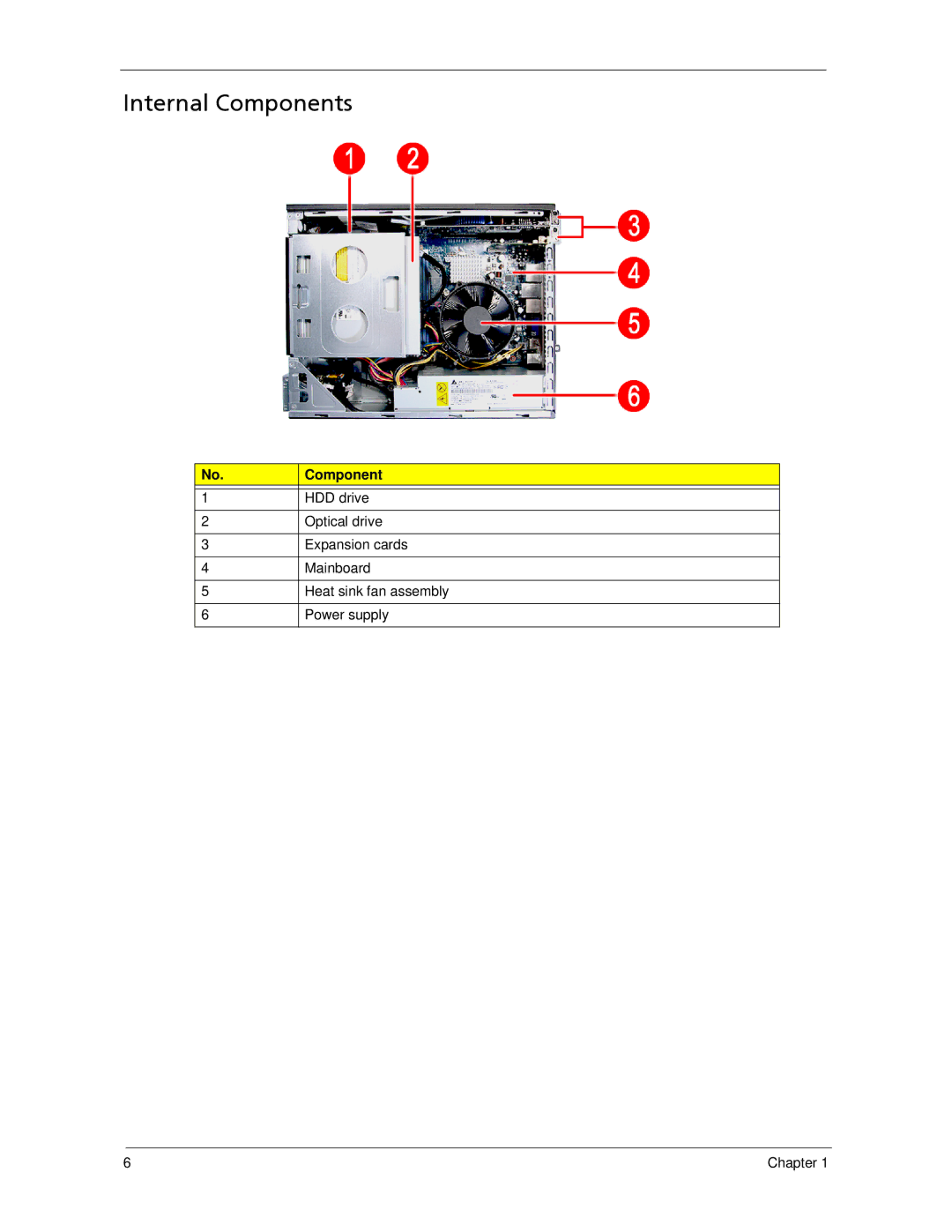
HDD drive
Optical drive
Expansion cards
Mainboard
Heat sink fan assembly
Power supply
6 | Chapter 1 |
No.
1
2
3
4
5
6
Component
HDD drive
Optical drive
Expansion cards
Mainboard
Heat sink fan assembly
Power supply
6 | Chapter 1 |