Rear Panel Function and Operation
1
2
MIC 3 INPUT
![]() cesonic KARAOKE AMPLIFIER
cesonic KARAOKE AMPLIFIER
MODEL:AM-145 INPUT:AC115V-230V
S/N
CITY OF INDUSTRY,CA,USA acesonic.com
VCD | TAPE | DVD | VIDEO OUT |
VIDEO
INPUT
OUTPUT
L | L |
AUDIO
INPUT
R |
|
|
|
| R |
VCD | TAPE | DVD | AUDIO OUT | LINE | SUB |
+ RIGHT - | - LEFT + |
SPEAKER SYSTEM(4-8 次 )
CAUTION
RISK OF ELECTRIC
SHOCK DO NOT OPEN
WARNING:TO REDUCE THE RISK OF FIRE OR ELECTRIC SHOCK
DO NOT EXPOSE THIS APPLIANCE TO RAIN OR MOISTORE
GND
VOLTAGE SELECT
![]() 115V
115V
AC INPUT ~230/115V 50/60Hz
AC 115V INPUT FUSE 250V/T5A
AC 230V INPUT FUSE 250V/T2.5A
3 | 4 | 5 | 6 | 7 | 8 | 9 | 10 | 11 |
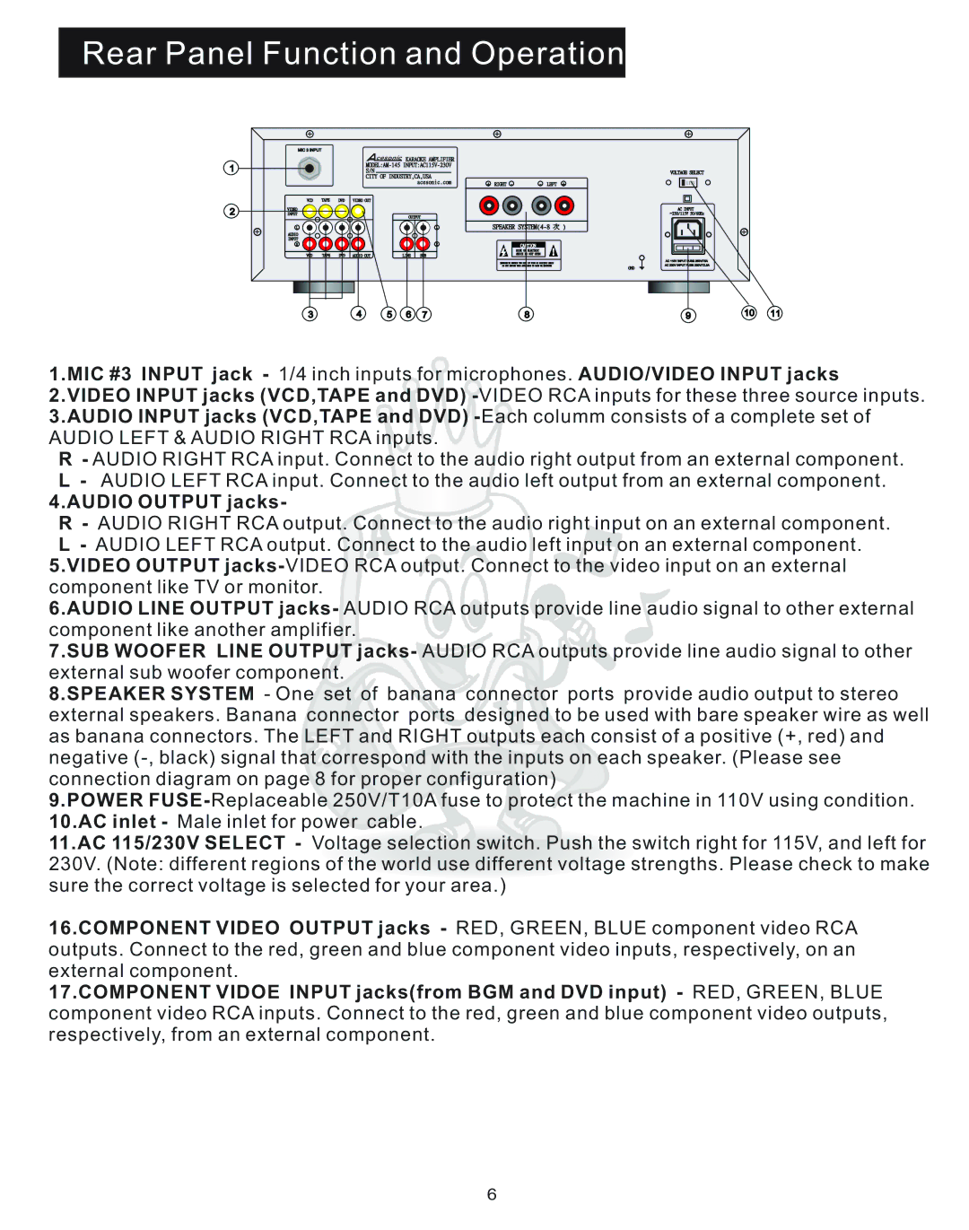
1.MIC #3 INPUT jack - 1/4 inch inputs for microphones. AUDIO/VIDEO INPUT jacks 2.VIDEO INPUT jacks (VCD,TAPE and DVD)
R- AUDIO RIGHT RCA input. Connect to the audio right output from an external component. L - AUDIO LEFT RCA input. Connect to the audio left output from an external component.
4.AUDIO OUTPUT jacks-
R- AUDIO RIGHT RCA output. Connect to the audio right input on an external component. L - AUDIO LEFT RCA output. Connect to the audio left input on an external component.
5.VIDEO OUTPUT
6.AUDIO LINE OUTPUT jacks- AUDIO RCA outputs provide line audio signal to other external component like another amplifier.
7.SUB WOOFER LINE OUTPUT jacks- AUDIO RCA outputs provide line audio signal to other external sub woofer component.
8.SPEAKER SYSTEM - One set of banana connector ports provide audio output to stereo external speakers. Banana connector ports designed to be used with bare speaker wire as well as banana connectors. The LEFT and RIGHT outputs each consist of a positive (+, red) and negative
9.POWER
11.AC 115/230V SELECT - Voltage selection switch. Push the switch right for 115V, and left for 230V. (Note: different regions of the world use different voltage strengths. Please check to make sure the correct voltage is selected for your area.)
16.COMPONENT VIDEO OUTPUT jacks - RED, GREEN, BLUE component video RCA outputs. Connect to the red, green and blue component video inputs, respectively, on an external component.
17.COMPONENT VIDOE INPUT jacks(from BGM and DVD input) - RED, GREEN, BLUE component video RCA inputs. Connect to the red, green and blue component video outputs, respectively, from an external component.
6