Input / Output Board L.E.D. Indicators
Inputs
ESTOP – (RED L.E.D.): This L.E.D. will indicate the status of the
GAS_V – (RED L.E.D.): This L.E.D. will indicate the status of the gas valve. If the gas valve is open (ON), then the L.E.D. is on.
BRHL – (RED L.E.D.): This L.E.D. will indicate the status of the burner high limit disk. If the disk is closed (temperature below 330º F [166º C]), then the L.E.D. is ON.
SAIL – (RED L.E.D.): This L.E.D. will indicate the status of the sail switch. If the switch is closed, then the L.E.D. is ON.
EXHL – (RED L.E.D.): This L.E.D. will indicate the status of the exhaust high limit disk. If the disk is closed (temperature below 225º F [107º C]), then the L.E.D. is ON.
MAIN – (RED L.E.D.): This L.E.D. will indicate the status of the main door. If the door is closed, then the L.E.D. is ON.
LINT – (RED L.E.D.): This L.E.D. will indicate the status of the lint drawer. If the drawer is closed, then the L.E.D. is ON.
FUSE – (RED L.E.D.): This L.E.D. will indicate the status of the control voltage.
Outputs
STEAM – (GREEN L.E.D.): This L.E.D. will indicate the status of the steam injection output. If the request to turn on the steam injection is made, then the L.E.D. is ON.
_HEAT – (GREEN L.E.D.): This L.E.D. will indicate the status of the heat output. If the request to turn on the heater is made, then the L.E.D. is ON.
AIR – (GREEN L.E.D.): This L.E.D. will indicate the status of the air jet output. If the request to turn on the air jet is made, then the L.E.D. is ON.
REV – (GREEN L.E.D.): This L.E.D. will indicate the status of the tumbler reverse direction output. If the request to tumble the drum in the reverse direction is made, then the L.E.D. is ON.
FWD – (GREEN L.E.D.): This L.E.D. will indicate the status of the tumbler forward direction output. If the request to tumble the drum in the forward direction is made, then the L.E.D. is ON.
FAN – (GREEN L.E.D.): This L.E.D. will indicate the status of the fan output. If the request to turn on the fan (blower) is made, then the L.E.D. is ON.
Technical Information ________________
The following section contains various technical information important to the service person in servicing and maintaining the dryer.
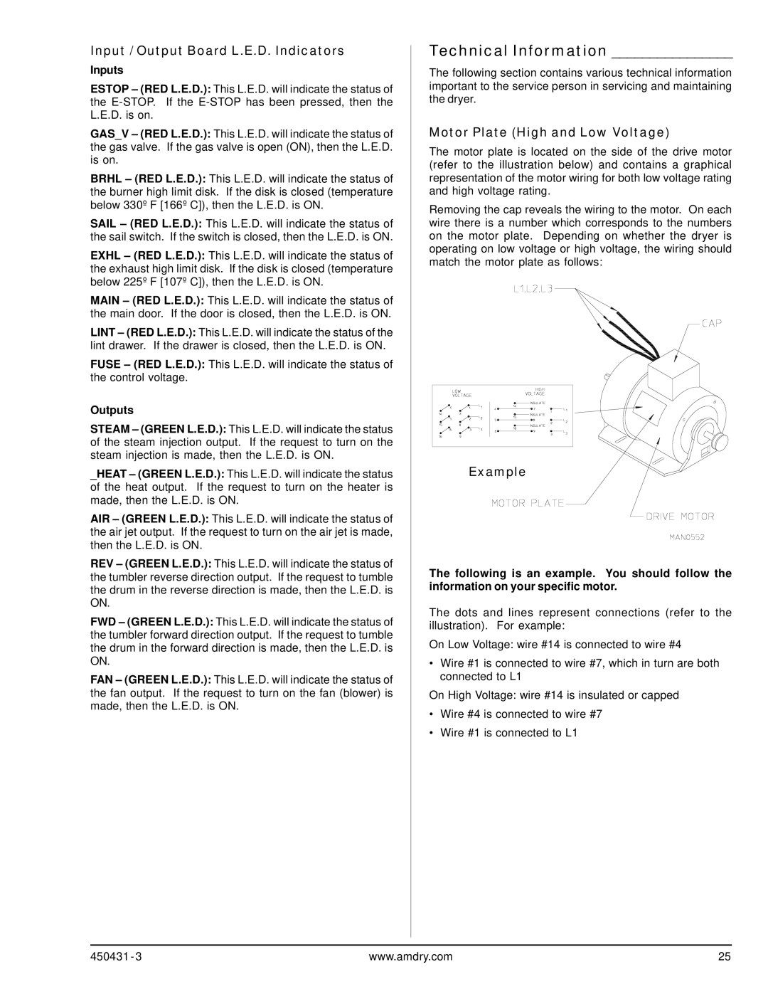
Motor Plate (High and Low Voltage)
The motor plate is located on the side of the drive motor (refer to the illustration below) and contains a graphical representation of the motor wiring for both low voltage rating and high voltage rating.
Removing the cap reveals the wiring to the motor. On each wire there is a number which corresponds to the numbers on the motor plate. Depending on whether the dryer is operating on low voltage or high voltage, the wiring should match the motor plate as follows:
Example
The following is an example. You should follow the information on your specific motor.
The dots and lines represent connections (refer to the illustration). For example:
On Low Voltage: wire #14 is connected to wire #4
•Wire #1 is connected to wire #7, which in turn are both connected to L1
On High Voltage: wire #14 is insulated or capped
•Wire #4 is connected to wire #7
•Wire #1 is connected to L1
450431 - 3 | www.amdry.com | 25 |