Clean the shaft and slide the pillow block bearings off of the shaft.
Reverse these steps to install new pillow block bearings.
NOTE: Check belt adjustment and readjust if necessary.
To Replace Speed Reducing Shaft Bearings
Discontinue electrical power to the dryer. Remove the lint drawer.
Remove the lint door.
Loosen and roll
Loosen and roll
Remove the four bolts holding the two speed reducing shaft pillow block bearings in place and remove shaft assembly from dryer.
To remove front or rear pulley follow steps in “To Replace Drive Shaft Pulleys”.
Loosen and remove the two setscrews in the front/rear pillow block bearing.
Clean the shaft and slide the bearings off of the shaft. Install new bearing by reversing these procedures. Reestablish electrical power to the dryer.
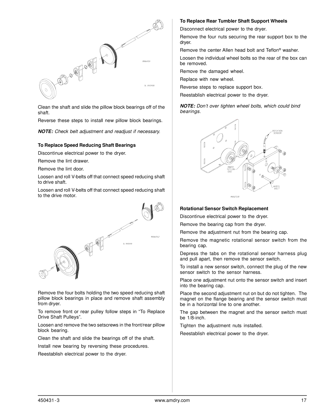
To Replace Rear Tumbler Shaft Support Wheels
Disconnect electrical power to the dryer.
Remove the four nuts securing the rear support box to the dryer.
Remove the center Allen head bolt and Teflon® washer.
Loosen the individual wheel bolts so the rear of the box can be removed.
Remove the damaged wheel. Replace with new wheel.
Reverse steps to replace support box. Reestablish electrical power to the dryer.
NOTE: Don’t over tighten wheel bolts, which could bind bearings.
Rotational Sensor Switch Replacement
Discontinue electrical power to the dryer. Remove the bearing cap from the dryer.
Remove the adjustment nut from the bearing cap.
Remove the magnetic rotational sensor switch from the bearing cap.
Depress the tabs on the rotational sensor harness plug and pull apart, then remove the sensor switch.
To install a new sensor switch, connect the plug of the new sensor switch to the sensor harness.
Place one adjustment nut onto the sensor switch and insert into the bearing cap.
Place the second adjustment nut on but do not tighten. The magnet on the flange bearing and the sensor switch must be in a horizontal line to one another.
The gap between the magnet and the sensor switch must be
Tighten the adjustment nuts installed. Reestablish electrical power to the dryer.
450431 - 3 | www.amdry.com | 17 |