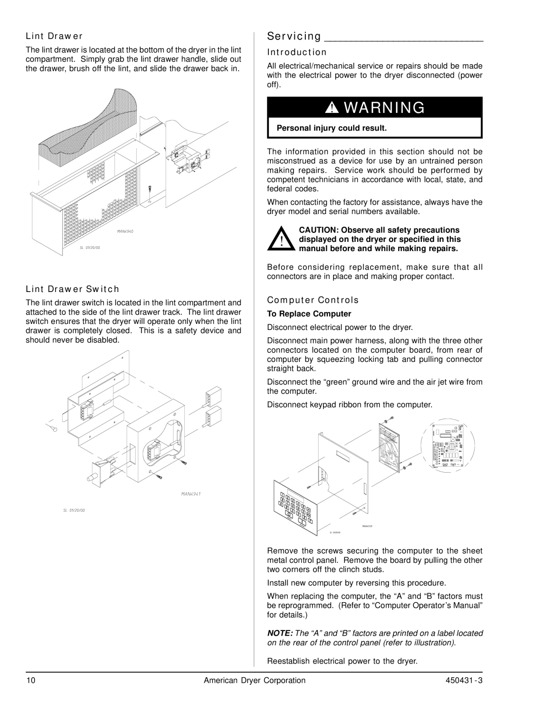
Lint Drawer | Servicing ______________________________ | ||
The lint drawer is located at the bottom of the dryer in the lint | Introduction | ||
compartment. Simply grab the lint drawer handle, slide out | All electrical/mechanical service or repairs should be made | ||
the drawer, brush off the lint, and slide the drawer back in. | |||
| with the electrical power to the dryer disconnected (power | ||
| off). |
| |
|
| ▲! WARNING | |
| Personal injury could result. | ||
| The information provided in this section should not be | ||
| misconstrued as a device for use by an untrained person | ||
| making repairs. Service work should be performed by | ||
| competent technicians in accordance with local, state, and | ||
| federal codes. | ||
| When contacting the factory for assistance, always have the | ||
| dryer model and serial numbers available. | ||
| ! | CAUTION: Observe all safety precautions | |
| displayed on the dryer or specified in this | ||
|
| ||
|
| manual before and while making repairs. | |
| Before considering replacement, make sure that all | ||
| connectors are in place and making proper contact. | ||
Lint Drawer Switch | Computer Controls | ||
The lint drawer switch is located in the lint compartment and | |||
attached to the side of the lint drawer track. The lint drawer | To Replace Computer | ||
switch ensures that the dryer will operate only when the lint | Disconnect electrical power to the dryer. | ||
drawer is completely closed. This is a safety device and | |||
|
| ||
should never be disabled. | Disconnect main power harness, along with the three other | ||
| connectors located on the computer board, from rear of | ||
| computer by squeezing locking tab and pulling connector | ||
| straight back. | ||
| Disconnect the “green” ground wire and the air jet wire from | ||
| the computer. | ||
| Disconnect keypad ribbon from the computer. | ||
Remove the screws securing the computer to the sheet metal control panel. Remove the board by pulling the other two corners off the clinch studs.
Install new computer by reversing this procedure.
When replacing the computer, the “A” and “B” factors must be reprogrammed. (Refer to “Computer Operator’s Manual” for details.)
NOTE: The “A” and “B” factors are printed on a label located on the rear of the control panel (refer to illustration).
Reestablish electrical power to the dryer.
10 | American Dryer Corporation | 450431 - 3 |