Series
SignalOn® Series
RF Signal Management
Passives: Introduction
The SignalOn® Series, combined with the innovative cable management of the chassis, provides engineers with a variety of products to simplify the RF signal management challenge.
Passives:
RF Splitter/Combiner Modules 5 MHz to 1 GHz
Catalog Number
N - M __ __ __ __ __ __
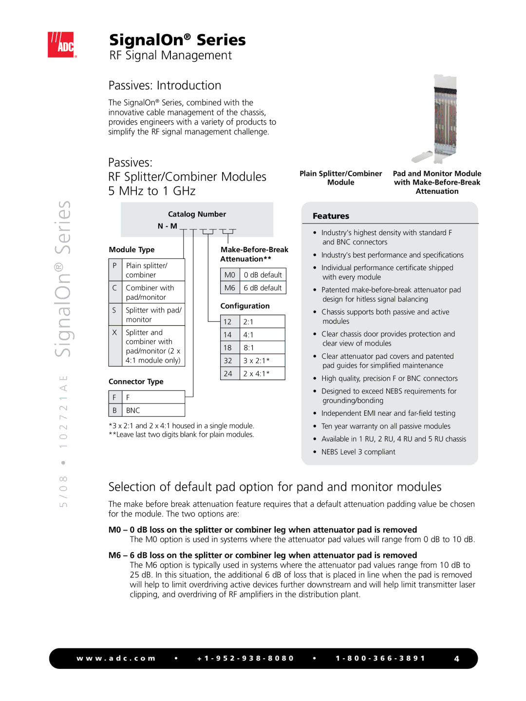
Plain Splitter/Combiner | Pad and Monitor Module |
Module | with |
| Attenuation |
Features
• Industry's highest density with standard F |
and BNC connectors |
7 2 1 A E SignalOn®
Module Type
PPlain splitter/ combiner
CCombiner with pad/monitor
SSplitter with pad/ monitor
XSplitter and combiner with pad/monitor (2 x 4:1 module only)
Connector Type
F F
BBNC
M0 0 dB default
M6 6 dB default
Configuration
122:1
144:1
188:1
32 3 x 2:1*
24 2 x 4:1*
• Industry's best performance and specifications |
• Individual performance certificate shipped |
with every module |
• Patented |
design for hitless signal balancing |
• Chassis supports both passive and active |
modules |
• Clear chassis door provides protection and |
clear view of modules |
• Clear attenuator pad covers and patented |
pad guides for simplified maintenance |
• High quality, precision F or BNC connectors |
• Designed to exceed NEBS requirements for |
grounding/bonding |
• Independent EMI near and |
8 • 1 0 2
*3 x 2:1 and 2 x 4:1 housed in a single module. **Leave last two digits blank for plain modules.
• Ten year warranty on all passive modules | |
• | Available in 1 RU, 2 RU, 4 RU and 5 RU chassis |
• | NEBS Level 3 compliant |
5 / 0
Selection of default pad option for pand and monitor modules
The make before break attenuation feature requires that a default attenuation padding value be chosen for the module. The two options are:
M0 – 0 dB loss on the splitter or combiner leg when attenuator pad is removed
The M0 option is used in systems where the attenuator pad values will range from 0 dB to 10 dB.
M6 – 6 dB loss on the splitter or combiner leg when attenuator pad is removed
The M6 option is typically used in systems where the attenuator pad values range from 10 dB to 25 dB. In this situation, the additional 6 dB of loss that is placed in line when the pad is removed will help to limit overdriving active devices further downstream and will help limit transmitter laser clipping, and overdriving of RF amplifiers in the distribution plant.
w w w . a d c . c o m | • | + 1 - 9 5 2 - 9 3 8 - 8 0 8 0 | • | 1 - 8 0 0 - 3 6 6 - 3 8 9 1 | 4 |