GTP-602 specifications
The Adcom GTP-602 is a highly regarded audio/video receiver that brings together advanced technology and outstanding performance in a compact package. Ideal for both music and home theater enthusiasts, this receiver incorporates multiple features that enhance audio and video playback while ensuring user-friendly operation.One of the most notable features of the GTP-602 is its support for a wide range of audio formats. This receiver is equipped with advanced digital signal processing to provide expansive stereo sound and multi-channel surround sound configurations. It supports various formats, offering compatibility with Dolby Digital, DTS, and even advanced formats such as Dolby Pro Logic II, making it suitable for diverse audio content.
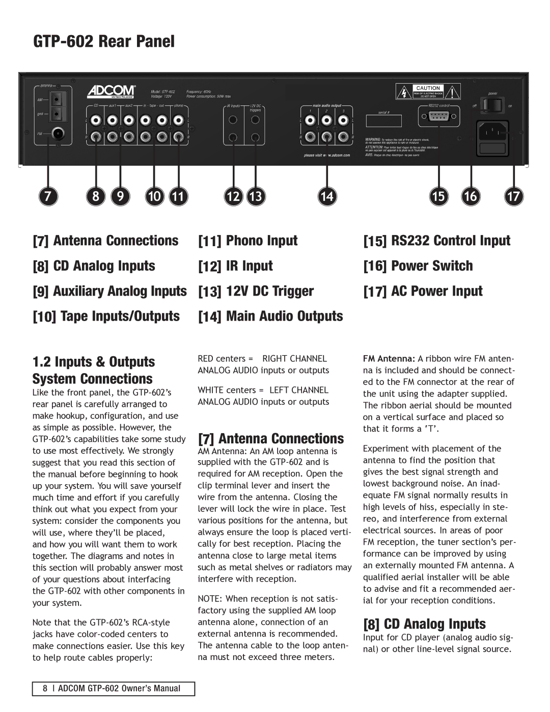
The GTP-602 also boasts a comprehensive input selection that enables users to connect various devices seamlessly. It provides multiple analog and digital inputs, including optical and coaxial, allowing users to hook up their CD players, gaming consoles, and digital media players effortlessly. Additionally, the receiver features a phono input for vinyl lovers, showcasing Adcom's commitment to catering to audiophiles.
In terms of video technology, the Adcom GTP-602 is equipped with high-quality video processing capabilities. It supports multiple video formats, including composite, S-Video, and component video, ensuring compatibility with a range of display devices. Furthermore, the GTP-602 delivers impressive picture quality with low distortion and high fidelity.
User-friendliness is another hallmark of the GTP-602. The receiver comes with an intuitive remote control that simplifies operation. It allows users to navigate through various settings, adjust sound modes, and switch between sources with ease. An easy-to-read display provides essential information, enhancing the overall usability of the device.
The build quality of the Adcom GTP-602 is sturdy and reliable, ensuring longevity and durability. This receiver features high-quality components that contribute to its overall performance, making it a favorite among both casual listeners and audio professionals. Overall, the Adcom GTP-602 is a versatile audio/video receiver that combines advanced features with excellent performance, making it an excellent choice for anyone looking to elevate their audio and visual experience.

