ADDONICS TECHNOLOGIES
Model: CDC5HXAES
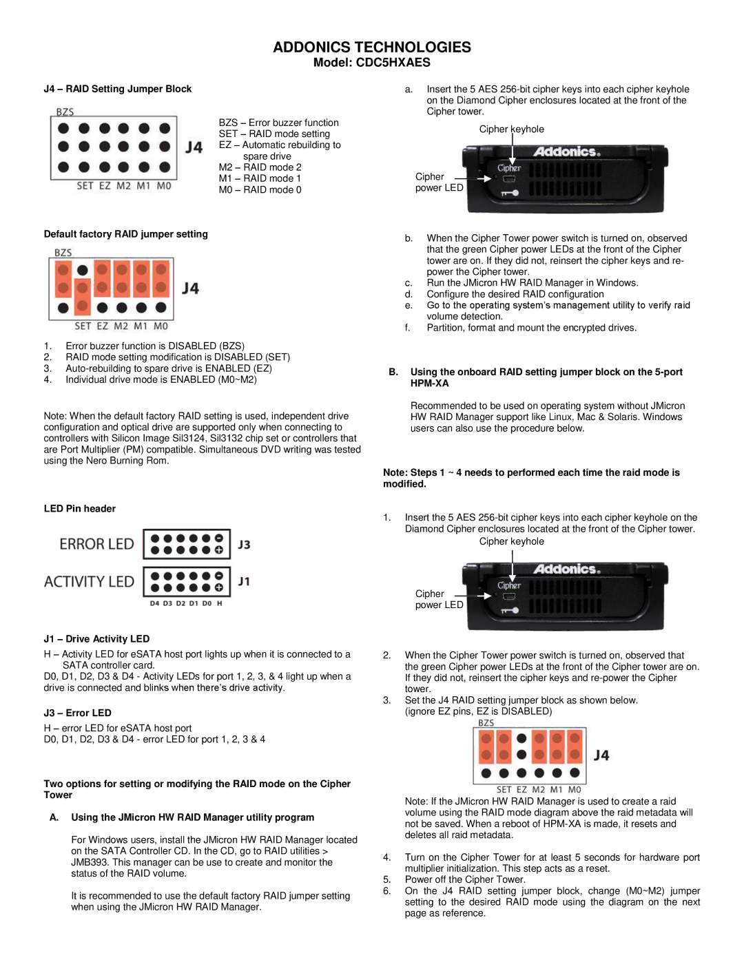
J4 – RAID Setting Jumper Block
BZS – Error buzzer function SET – RAID mode setting EZ – Automatic rebuilding to
spare drive M2 – RAID mode 2 M1 – RAID mode 1 M0 – RAID mode 0
Default factory RAID jumper setting
1.Error buzzer function is DISABLED (BZS)
2.RAID mode setting modification is DISABLED (SET)
3.
4.Individual drive mode is ENABLED (M0~M2)
Note: When the default factory RAID setting is used, independent drive configuration and optical drive are supported only when connecting to controllers with Silicon Image Sil3124, Sil3132 chip set or controllers that are Port Multiplier (PM) compatible. Simultaneous DVD writing was tested using the Nero Burning Rom.
LED Pin header
J1 – Drive Activity LED
H – Activity LED for eSATA host port lights up when it is connected to a SATA controller card.
D0, D1, D2, D3 & D4 - Activity LEDs for port 1, 2, 3, & 4 light up when a drive is connected and blinks when there’s drive activity.
J3 – Error LED
H – error LED for eSATA host port
D0, D1, D2, D3 & D4 - error LED for port 1, 2, 3 & 4
Two options for setting or modifying the RAID mode on the Cipher Tower
A.Using the JMicron HW RAID Manager utility program
For Windows users, install the JMicron HW RAID Manager located on the SATA Controller CD. In the CD, go to RAID utilities > JMB393. This manager can be use to create and monitor the status of the RAID volume.
It is recommended to use the default factory RAID jumper setting when using the JMicron HW RAID Manager.
a.Insert the 5 AES
Cipher keyhole
Cipher ![]() power LED
power LED
b.When the Cipher Tower power switch is turned on, observed that the green Cipher power LEDs at the front of the Cipher tower are on. If they did not, reinsert the cipher keys and re- power the Cipher tower.
c.Run the JMicron HW RAID Manager in Windows.
d.Configure the desired RAID configuration
e.Go to the operating system’s management utility to verify raid volume detection.
f.Partition, format and mount the encrypted drives.
B.Using the onboard RAID setting jumper block on the 5-port
HPM-XA
Recommended to be used on operating system without JMicron HW RAID Manager support like Linux, Mac & Solaris. Windows users can also use the procedure below.
Note: Steps 1 ~ 4 needs to performed each time the raid mode is modified.
1.Insert the 5 AES
Cipher keyhole
Cipher ![]() power LED
power LED
2.When the Cipher Tower power switch is turned on, observed that the green Cipher power LEDs at the front of the Cipher tower are on. If they did not, reinsert the cipher keys and
3.Set the J4 RAID setting jumper block as shown below. (ignore EZ pins, EZ is DISABLED)
Note: If the JMicron HW RAID Manager is used to create a raid volume using the RAID mode diagram above the raid metadata will not be saved. When a reboot of
4.Turn on the Cipher Tower for at least 5 seconds for hardware port multiplier initialization. This step acts as a reset.
5.Power off the Cipher Tower.
6.On the J4 RAID setting jumper block, change (M0~M2) jumper setting to the desired RAID mode using the diagram on the next page as reference.