Chapter 4. Configuration Overview and Examples
Example 1: IP Routing
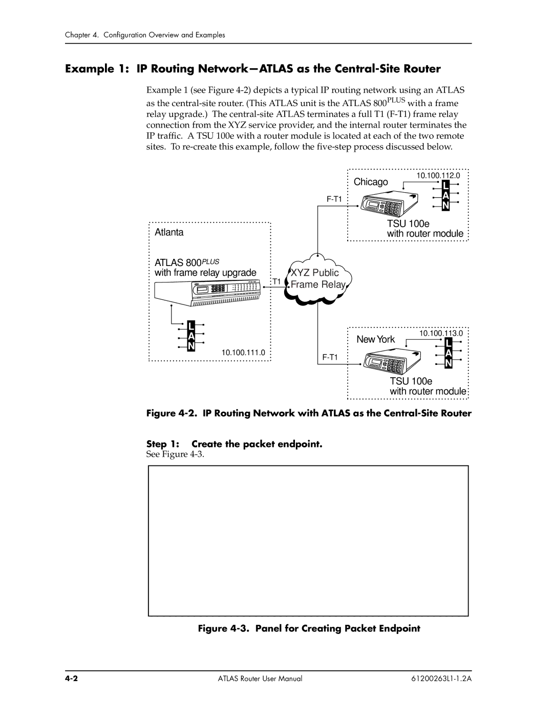
Example 1 (see Figure
Atlanta |
ATLAS 800PLUS |
with frame relay upgrade |
T1 |
L |
A |
N |
10.100.111.0 |
| Chicago | 10.100.112.0 |
| L | |
|
| |
| A | |
| N | |
|
| |
| TSU 100e | |
| with router module | |
XYZ Public
![]() Frame Relay
Frame Relay
| New York | 10.100.113.0 |
| L | |
|
| |
| A | |
| N | |
|
| |
| TSU 100e | |
| with router module | |
Figure 4-2. IP Routing Network with ATLAS as the Central-Site Router
Step 1: Create the packet endpoint.
See Figure
Figure 4-3. Panel for Creating Packet Endpoint
ATLAS Router User Manual |