Access

Maximum Number of DS0s that can

Module

be used per module


FXS

4


FXO

4


*OCU-DP

1


*DSO-DP

1


*U-BRITE

1


*E&M

1


Nx56/64

24

(special slot)


*Supported in TA 850 Q300.

Connections

All TA 850 BCU connections are made through the backplane connector. With the exception of power and the V.35 connector, all of the TA 850 rear panel connec- tors terminate on the BCU. These include Network T1, Clock source, Alarms, Fractional T1, and Management. Refer to the TA 850 System Installation and Mainte- nance Practice, part number 64200376L1- 5A, for addi- tional information on rear panel connections. Table 1 describes the T1 pinout connections.

Faceplate LED

The faceplate Network LED labeled T1 Network pro- vides status information for the network T1 using a col- or coded message format. Refer to Table 2.

4. TESTING

The TA 850 BCU provides a variety of test options for both the Network T1 and DS0 access modules. The face- plate of the BCU provides a bantam jack for local T1 test access. DS0 test access for the digital access modules (OCU DP, DS0 DP, U-BR1TE) is provided via bantam jacks on the faceplate of each unit.

Faceplate Bantam Jack

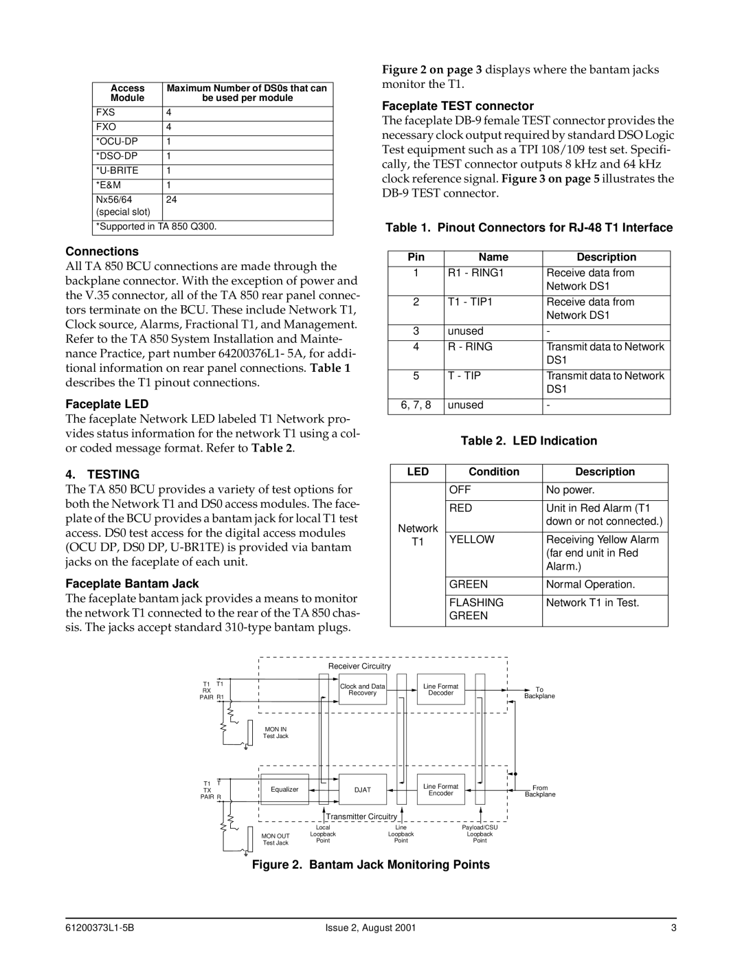
The faceplate bantam jack provides a means to monitor the network T1 connected to the rear of the TA 850 chas- sis. The jacks accept standard 310-type bantam plugs.

Figure 2 on page 3 displays where the bantam jacks monitor the T1.

Faceplate TEST connector

The faceplate DB-9 female TEST connector provides the necessary clock output required by standard DSO Logic Test equipment such as a TPI 108/109 test set. Specifi- cally, the TEST connector outputs 8 kHz and 64 kHz clock reference signal. Figure 3 on page 5 illustrates the DB-9 TEST connector.

Table 1. Pinout Connectors for RJ-48 T1 Interface

Pin

Name

Description


1

R1 - RING1

Receive data from


Network DS1


2

T1 - TIP1

Receive data from


Network DS1


3

unused

-


4

R - RING

Transmit data to Network


DS1


5

T - TIP

Transmit data to Network


DS1


6, 7, 8

unused

-


Table 2. LED Indication

LED

Condition

Description


OFF

No power.


RED

Unit in Red Alarm (T1

Network


down or not connected.)


T1

YELLOW

Receiving Yellow Alarm


(far end unit in Red


Alarm.)


GREEN

Normal Operation.


FLASHING

Network T1 in Test.


GREEN


Receiver Circuitry


T1

T1


Clock and Data

Line Format

To

RX


Recovery

Decoder

PAIR R1


Backplane


MON IN


Test Jack


T1

T


DJAT

Line Format

From

TX

Equalizer


PAIR R


Encoder

Backplane


Transmitter Circuitry


Local

Line


Payload/CSU


MON OUT

Loopback

Loopback


Loopback


Point

Point


Point


Test Jack


Figure 2. Bantam Jack Monitoring Points

61200373L1-5B

Issue 2, August 2001

3

Page 3
Image 3
ADTRAN 850 specifications Testing

850 specifications

ADTRAN 850 is a high-performance digital subscriber line (DSL) solution designed to meet the ever-evolving demands of telecommunications providers and their customers. This innovative platform enables operators to deliver high-speed broadband services over existing copper infrastructure, significantly enhancing the user experience.

One of the standout features of the ADTRAN 850 is its support for G.fast technology. G.fast is a next-generation access technology that allows for data rates of up to 1 Gbps over short distances. Utilizing advanced modulation techniques, G.fast is capable of providing ultra-broadband speeds to customers residing within close proximity to the distribution point. This capability significantly expands the service options for operators seeking to improve their last-mile connectivity.

The ADTRAN 850 also integrates with VDSL2, allowing service providers to leverage their existing DSL networks effectively. VDSL2 enhances bandwidth capabilities and can deliver speeds of up to 100 Mbps downstream and 100 Mbps upstream. This dual compatibility ensures that operators can maximize their investments while transitioning to more advanced technologies.

In terms of characteristics, the ADTRAN 850 is built with robustness and scalability in mind. It is designed to accommodate a wide range of deployments, from small rural communities to dense urban areas. The platform supports multiple service types, including residential and business services, and allows for customizable bandwidth allocation based on user needs.

Moreover, the ADTRAN 850 is equipped with advanced management capabilities. Its web-based management interface provides operators with actionable insights into network performance and customer usage patterns. This ensures proactive maintenance and optimization of the network, which is essential for maintaining high service quality.

Security features are also prominent in the ADTRAN 850, with built-in encryption and secure access protocols to protect sensitive customer data. This focus on security aligns with increasing regulatory requirements and customer expectations regarding data privacy.

In conclusion, the ADTRAN 850 is a versatile and powerful DSL solution that stands out for its support of G.fast and VDSL2 technologies, remarkable scalability, and robust management capabilities. Its ability to provide high-speed broadband services over existing copper lines makes it an essential tool for telecommunications providers looking to enhance their service offerings and improve customer satisfaction in today’s digital age.