850 specifications
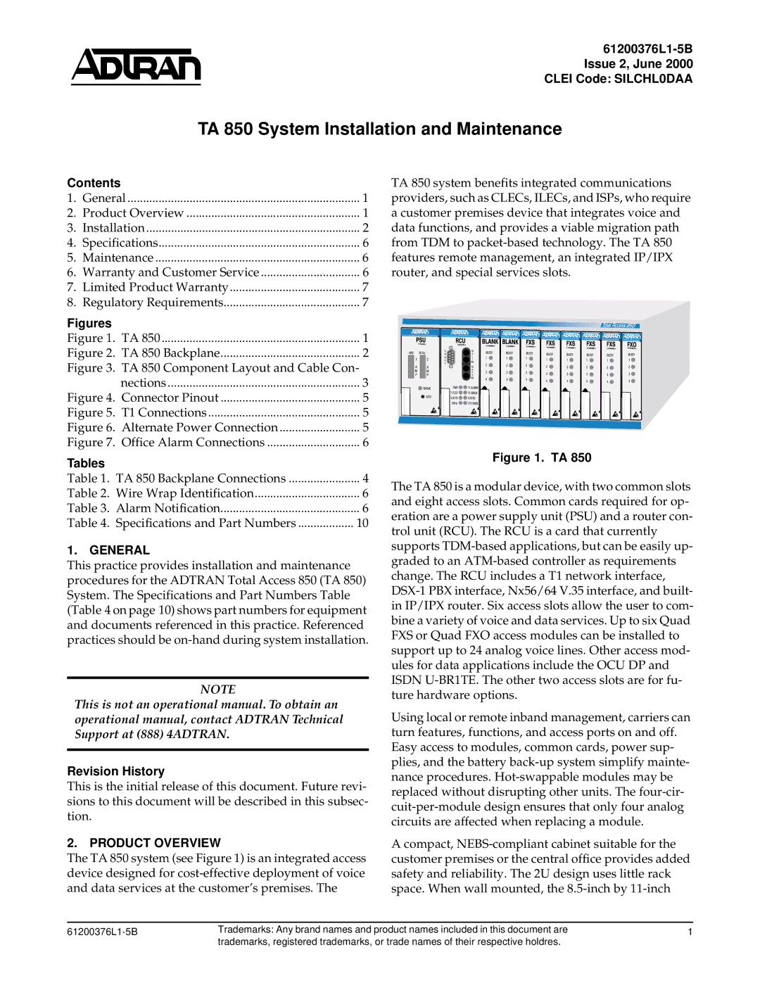
ADTRAN 850 is a high-performance digital subscriber line (DSL) solution designed to meet the ever-evolving demands of telecommunications providers and their customers. This innovative platform enables operators to deliver high-speed broadband services over existing copper infrastructure, significantly enhancing the user experience.One of the standout features of the ADTRAN 850 is its support for G.fast technology. G.fast is a next-generation access technology that allows for data rates of up to 1 Gbps over short distances. Utilizing advanced modulation techniques, G.fast is capable of providing ultra-broadband speeds to customers residing within close proximity to the distribution point. This capability significantly expands the service options for operators seeking to improve their last-mile connectivity.
The ADTRAN 850 also integrates with VDSL2, allowing service providers to leverage their existing DSL networks effectively. VDSL2 enhances bandwidth capabilities and can deliver speeds of up to 100 Mbps downstream and 100 Mbps upstream. This dual compatibility ensures that operators can maximize their investments while transitioning to more advanced technologies.
In terms of characteristics, the ADTRAN 850 is built with robustness and scalability in mind. It is designed to accommodate a wide range of deployments, from small rural communities to dense urban areas. The platform supports multiple service types, including residential and business services, and allows for customizable bandwidth allocation based on user needs.
Moreover, the ADTRAN 850 is equipped with advanced management capabilities. Its web-based management interface provides operators with actionable insights into network performance and customer usage patterns. This ensures proactive maintenance and optimization of the network, which is essential for maintaining high service quality.
Security features are also prominent in the ADTRAN 850, with built-in encryption and secure access protocols to protect sensitive customer data. This focus on security aligns with increasing regulatory requirements and customer expectations regarding data privacy.
In conclusion, the ADTRAN 850 is a versatile and powerful DSL solution that stands out for its support of G.fast and VDSL2 technologies, remarkable scalability, and robust management capabilities. Its ability to provide high-speed broadband services over existing copper lines makes it an essential tool for telecommunications providers looking to enhance their service offerings and improve customer satisfaction in today’s digital age.

