Grounding Instructions

This section provides grounding instruction informa- tion from the Underwriters' Laboratory UL 1950 Stan- dard for Safety: Information Technology Equipment.

An equipment grounding conductor that is not smaller in size than the ungrounded branch-circuit supply con- ductors is to be installed as part of the circuit that sup- plies the product or system. Bare, covered, or insulated grounding conductors are acceptable. Individually covered or insulated equipment grounding conductors shall have a continuous outer finish that is either green, or green with one or more yellow stripes. The equip- ment grounding conductor is to be connected to ground at the service equipment.

The attachment-plug receptacles in the vicinity of the product or system are all to be of a grounding type, and the equipment grounding conductors serving these re- ceptacles are to be connected to earth ground at the ser- vice equipment.

A supplementary equipment grounding conductor shall be installed between the product or system and ground that is in addition to the equipment grounding conductor in the power supply cord.

The supplementary equipment grounding conductor shall not be smaller in size than the ungrounded branch-circuit supply conductors. The supplementary equipment grounding conductor shall be connected to the product at the terminal provided, and shall be con- nected to ground in a manner that will retain the ground connection when the product is unplugged from the receptacle. The connection to ground of the supplementary equipment grounding conductor shall be in compliance with the rules for terminating bonding jumpers at Part K or Article 250 of the National Electri- cal Code, ANSI/NFPA 70. Termination of the supple- mentary equipment grounding conductor is permitted to be made to building steel, to a metal electrical race- way system, or to any grounded item that is perma- nently and reliably connected to the electrical service equipment ground.

Install the Chassis

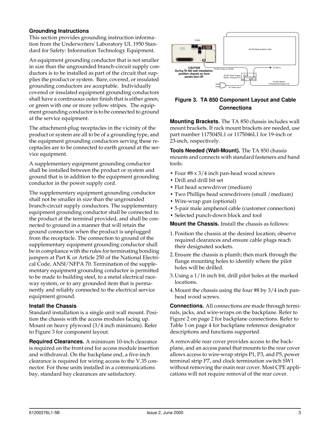
Standard installation is a single unit wall mount. Posi- tion the chassis with the access modules facing up. Mount on heavy plywood (3/4 inch minimum). Refer to Figure 3 for component layout.

Required Clearances. A minimum 10-inch clearance is required on the front end for access module insertion and withdrawal. On the backplane end, a five-inch clearance is required for wiring access to the V.35 con- nector. For those units installed in a communications bay, standard bay clearances are satisfactory.


TA 850


T1


WARNING:

V.35


20Hz FUSE

CRAFT 10 BASE T

-48 VDC Backup Battery Pack

BEFORE REAR COVER

MUST BE REMOVED


DSX-1


DC


POWER


CAUTION

To Alarms

During TA 850 wall installation,

-54 VDC Output to TA 850


position chassis so front

AC/DC Power Supply

panels face UP.

Battery Charging Unit

+ -

-54 VDC Battery

Charging/Discharging Line

AC Power Input

Figure 3. TA 850 Component Layout and Cable

Connections

Mounting Brackets. The TA 850 chassis includes wall mount brackets. If rack mount brackets are needed, use part number 1175045L1 or 1175046L1 for 19-inch or 23-inch, respectively.

Tools Needed (Wall-Mount). The TA 850 chassis mounts and connects with standard fasteners and hand tools:

Four #8 x 3/4 inch pan-head wood screws

Drill and drill bit set

Flat head screwdriver (medium)

Two Phillips head screwdrivers (small /medium)

Wire-wrap gun (optional)

5-pair male amphenol cable (customer connection)

Selected punch-down block and tool

Mount the Chassis. Install the chassis as follows:

1.Position the chassis at the desired location; observe required clearances and ensure cable plugs reach their designated sockets.

2.Ensure the chassis is plumb; then mark through the flange mounting holes to identify where the pilot holes will be drilled.

3.Using a 1/16 inch bit, drill pilot holes at the marked locations.

4.Mount the chassis using the four #8 by 3/4 inch pan- head wood screws.

Connections. All connections are made through termi- nals, jacks, and wire-wraps on the backplane. Refer to Figure 2 on page 2 for backplane connections. Refer to Table 1 on page 4 for backplane reference designator descriptions and functions supported.

A removable rear cover provides access to the back- plane, and an access panel that mounts to the rear cover allows access to wire-wrap strips P1, P3, and P5, power terminal strip P7, and clock termination switch SW1 without removing the main rear cover. Most CPE appli- cations will not require removal of the rear cover.

61200376L1-5B

Issue 2, June 2000

3

Page 3
Image 3
ADTRAN 850 specifications Grounding Instructions, Install the Chassis

850 specifications

ADTRAN 850 is a high-performance digital subscriber line (DSL) solution designed to meet the ever-evolving demands of telecommunications providers and their customers. This innovative platform enables operators to deliver high-speed broadband services over existing copper infrastructure, significantly enhancing the user experience.

One of the standout features of the ADTRAN 850 is its support for G.fast technology. G.fast is a next-generation access technology that allows for data rates of up to 1 Gbps over short distances. Utilizing advanced modulation techniques, G.fast is capable of providing ultra-broadband speeds to customers residing within close proximity to the distribution point. This capability significantly expands the service options for operators seeking to improve their last-mile connectivity.

The ADTRAN 850 also integrates with VDSL2, allowing service providers to leverage their existing DSL networks effectively. VDSL2 enhances bandwidth capabilities and can deliver speeds of up to 100 Mbps downstream and 100 Mbps upstream. This dual compatibility ensures that operators can maximize their investments while transitioning to more advanced technologies.

In terms of characteristics, the ADTRAN 850 is built with robustness and scalability in mind. It is designed to accommodate a wide range of deployments, from small rural communities to dense urban areas. The platform supports multiple service types, including residential and business services, and allows for customizable bandwidth allocation based on user needs.

Moreover, the ADTRAN 850 is equipped with advanced management capabilities. Its web-based management interface provides operators with actionable insights into network performance and customer usage patterns. This ensures proactive maintenance and optimization of the network, which is essential for maintaining high service quality.

Security features are also prominent in the ADTRAN 850, with built-in encryption and secure access protocols to protect sensitive customer data. This focus on security aligns with increasing regulatory requirements and customer expectations regarding data privacy.

In conclusion, the ADTRAN 850 is a versatile and powerful DSL solution that stands out for its support of G.fast and VDSL2 technologies, remarkable scalability, and robust management capabilities. Its ability to provide high-speed broadband services over existing copper lines makes it an essential tool for telecommunications providers looking to enhance their service offerings and improve customer satisfaction in today’s digital age.