TURN - UP & TROUBLESHOOTING GUIDE
PRICING AND AVAILABILITY 800.827.0807 TECHNICAL SUPPORT 800.923.8726 RETURN FOR REPAIR 256.963.8722 www.adtran.com
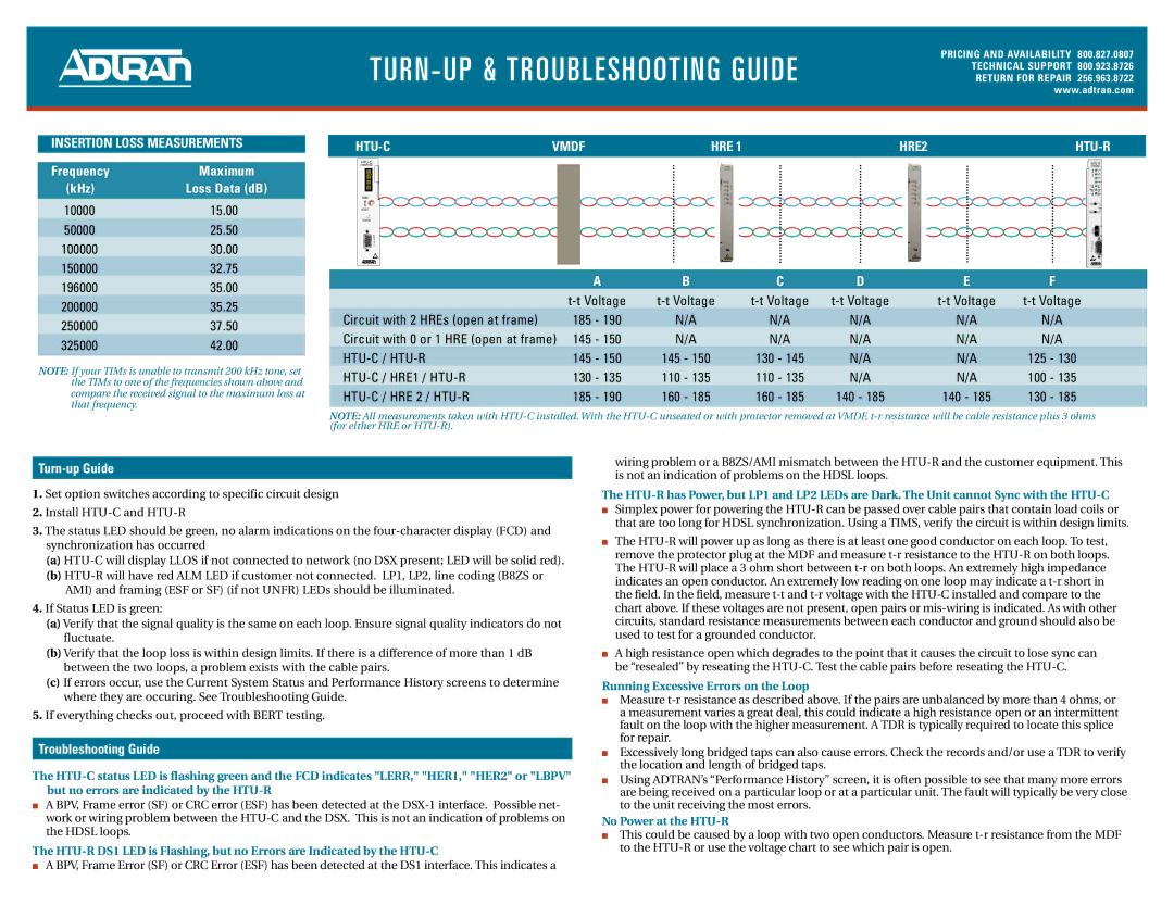
INSERTION LOSS MEASUREMENTS
Frequency | Maximum |
(kHz) | Loss Data (dB) |
10000 | 15.00 |
50000 | 25.50 |
100000 | 30.00 |
150000 | 32.75 |
196000 | 35.00 |
200000 | 35.25 |
250000 | 37.50 |
325000 | 42.00 |
NOTE: If your TIMs is unable to transmit 200 kHz tone, set the TIMs to one of the frequencies shown above and compare the received signal to the maximum loss at that frequency.
| VMDF | HRE 1 | HRE2 |
|
1246003L8 | 1246026L4 | |
| H | LP1 |
| D |
|
| S | LP2 |
| L | DS1 |
|
| ALM |
| ESF | SF |
| B8ZS | AMI |
| LLB | RLB |
MODE |
|
|
| LOC |
|
SELECT |
| LBK |
REM |
| |
|
| |
STATUS |
|
|
|
| TX |
| B | M |
| R | O |
R | G | N |
| RX | |
S |
|
|
2 | R |
|
3 |
| |
S |
| |
2 | 2 |
|
| 3 |
|
| 2 |
|
| A | B | C | D | E | F |
| ||||||
Circuit with 2 HREs (open at frame) | 185 - 190 | N/A | N/A | N/A | N/A | N/A |
Circuit with 0 or 1 HRE (open at frame) | 145 - 150 | N/A | N/A | N/A | N/A | N/A |
145 - 150 | 145 - 150 | 130 - 145 | N/A | N/A | 125 - 130 | |
130 - 135 | 110 - 135 | 110 - 135 | N/A | N/A | 100 - 135 | |
185 - 190 | 160 - 185 | 160 - 185 | 140 - 185 | 140 - 185 | 130 - 185 |
NOTE: All measurements taken with
Turn-up Guide
1.Set option switches according to specific circuit design
2.Install
3.The status LED should be green, no alarm indications on the
(a)
(b)
4.If Status LED is green:
(a)Verify that the signal quality is the same on each loop. Ensure signal quality indicators do not fluctuate.
(b)Verify that the loop loss is within design limits. If there is a difference of more than 1 dB between the two loops, a problem exists with the cable pairs.
(c)If errors occur, use the Current System Status and Performance History screens to determine where they are occuring. See Troubleshooting Guide.
5.If everything checks out, proceed with BERT testing.
Troubleshooting Guide
The
■A BPV, Frame error (SF) or CRC error (ESF) has been detected at the
The
■A BPV, Frame Error (SF) or CRC Error (ESF) has been detected at the DS1 interface. This indicates a
wiring problem or a B8ZS/AMI mismatch between the
The
■Simplex power for powering the
■The
■A high resistance open which degrades to the point that it causes the circuit to lose sync can be “resealed” by reseating the
Running Excessive Errors on the Loop
■Measure
■Excessively long bridged taps can also cause errors. Check the records and/or use a TDR to verify the location and length of bridged taps.
■Using ADTRAN’s “Performance History” screen, it is often possible to see that many more errors are being received on a particular loop or at a particular unit. The fault will typically be very close to the unit receiving the most errors.
No Power at the HTU-R
■This could be caused by a loop with two open conductors. Measure