3. CONNECTIONS
The FT1 DP occupies one card slot in a Nortel
level problems that may occur at installation or during operation of the FT1 HDSL system. The following subsections describe additional testing features conducted with the front panel Bantam jacks as well as other faceplate features.
Bantam Jack Description
5 V Ground
5 V Ground
DS0 Channel Rx Signal
DS0 Tx Bus Enable
Signaling Bus Enable
Rx Signaling Bus
Frame Ground
DS0 Bit Clock
HDSL Ring +5 V
|
|
| A1 | B1 |
| ||||||
|
|
| A2 | B2 |
| ||||||
|
|
| A3 | B3 |
| ||||||
|
|
| A4 | B4 |
| ||||||
|
|
| A5 | B5 |
| ||||||
|
|
| A6 | B6 |
| ||||||
|
|
| |||||||||
|
|
| A7 | B7 |
| ||||||
|
|
| A8 | B8 |
| ||||||
|
|
| A9 | B9 |
|
|
|
|
| ||
|
|
|
|
|
|
| |||||
|
|
| A10 | B10 |
|
|
|
| |||
|
|
| A11 | B11 |
|
|
|
| |||
|
|
|
|
|
| ||||||
|
|
| A12 | B12 |
|
|
|
| |||
|
|
| A13 | B13 |
|
|
|
| |||
|
|
| A14 | B14 |
|
|
| ||||
|
|
| A15 | B15 |
|
| |||||
|
|
| A16 | B16 |
| ||||||
|
|
| A17 | B17 |
| ||||||
|
|
| A18 | B18 |
| ||||||
|
|
| A19 | B19 |
| ||||||
|
|
| |||||||||
|
|
| A20 | B20 |
| ||||||
|
|
| |||||||||
|
|
| A21 | B21 |
| ||||||
|
|
| |||||||||
|
|
| A22 | B22 |
| ||||||
|
|
| A23 | B23 |
| ||||||
|
|
| A24 | B24 |
| ||||||
|
|
| A25 | B25 |
| ||||||
|
|
| A26 | B26 |
| ||||||
|
|
| A27 | B27 |
| ||||||
|
|
|
| ||||||||
|
|
| A28 | B28 |
| ||||||
|
|
| A29 | B29 |
| ||||||
|
|
| A30 | B30 |
| ||||||
|
|
| A31 | B31 |
| ||||||
|
|
| A32 | B32 |
|
| |||||
|
|
| A33 | B33 |
| ||||||
|
|
| A34 | B34 |
| ||||||
|
|
| |||||||||
|
|
| A35 | B35 |
|
| |||||
|
|
|
| ||||||||
|
|
|
|
|
|
|
|
|
|
|
|
DS0 Channel Tx Signal
DS0 Rx Clock
DS0 Tx Clock Carrier Group Alarm
DS0 Byte Clock
HDSL Tip
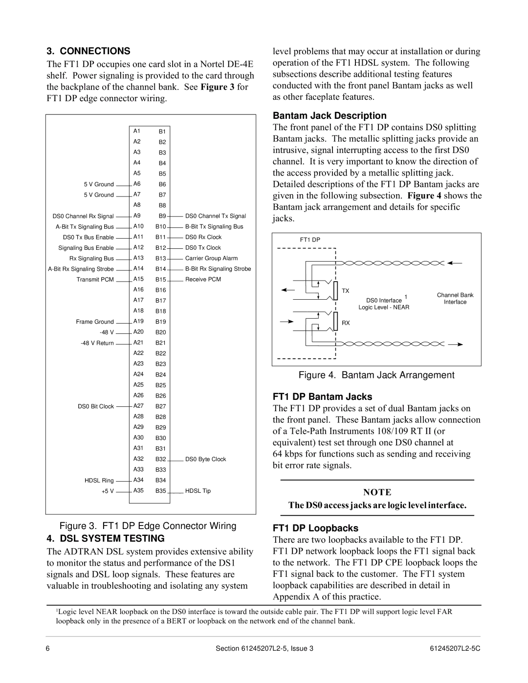
The front panel of the FT1 DP contains DS0 splitting Bantam jacks. The metallic splitting jacks provide an intrusive, signal interrupting access to the first DS0 channel. It is very important to know the direction of the access provided by a metallic splitting jack. Detailed descriptions of the FT1 DP Bantam jacks are given in the following subsection. Figure 4 shows the Bantam jack arrangement and details for specific jacks.
FT1 DP
TX | Channel Bank | |
DS0 Interface 1 | ||
Interface | ||
Logic Level - NEAR |
| |
RX |
|
Figure 4. Bantam Jack Arrangement
FT1 DP Bantam Jacks
The FT1 DP provides a set of dual Bantam jacks on the front panel. These Bantam jacks allow connection of a
64 kbps for functions such as sending and receiving bit error rate signals.
NOTE
The DS0 access jacks are logic level interface.
Figure 3. FT1 DP Edge Connector Wiring
4. DSL SYSTEM TESTING
The ADTRAN DSL system provides extensive ability to monitor the status and performance of the DS1 signals and DSL loop signals. These features are valuable in troubleshooting and isolating any system
FT1 DP Loopbacks
There are two loopbacks available to the FT1 DP. FT1 DP network loopback loops the FT1 signal back to the network. The FT1 DP CPE loopback loops the FT1 signal back to the customer. The FT1 system loopback capabilities are described in detail in Appendix A of this practice.
1Logic level NEAR loopback on the DS0 interface is toward the outside cable pair. The FT1 DP will support logic level FAR loopback only in the presence of a BERT or loopback on the network end of the channel bank.
6 | Section |