and manual switch settings by pressing the momentary Alternate Provisioning (AP) switch located on the front panel. If the channel unit is removed from the system, the unit retains previous provisioning information in nonvolatile Random Access Memory (RAM).
The REM indicator remains ON when the channel unit is operating based on Remote Provisioning, and is OFF when operating on manual switches. If the channel unit has never been remotely provisioned, the AP switch has no effect and the REM indicator remains OFF. See Table 3 for LED Indicators.
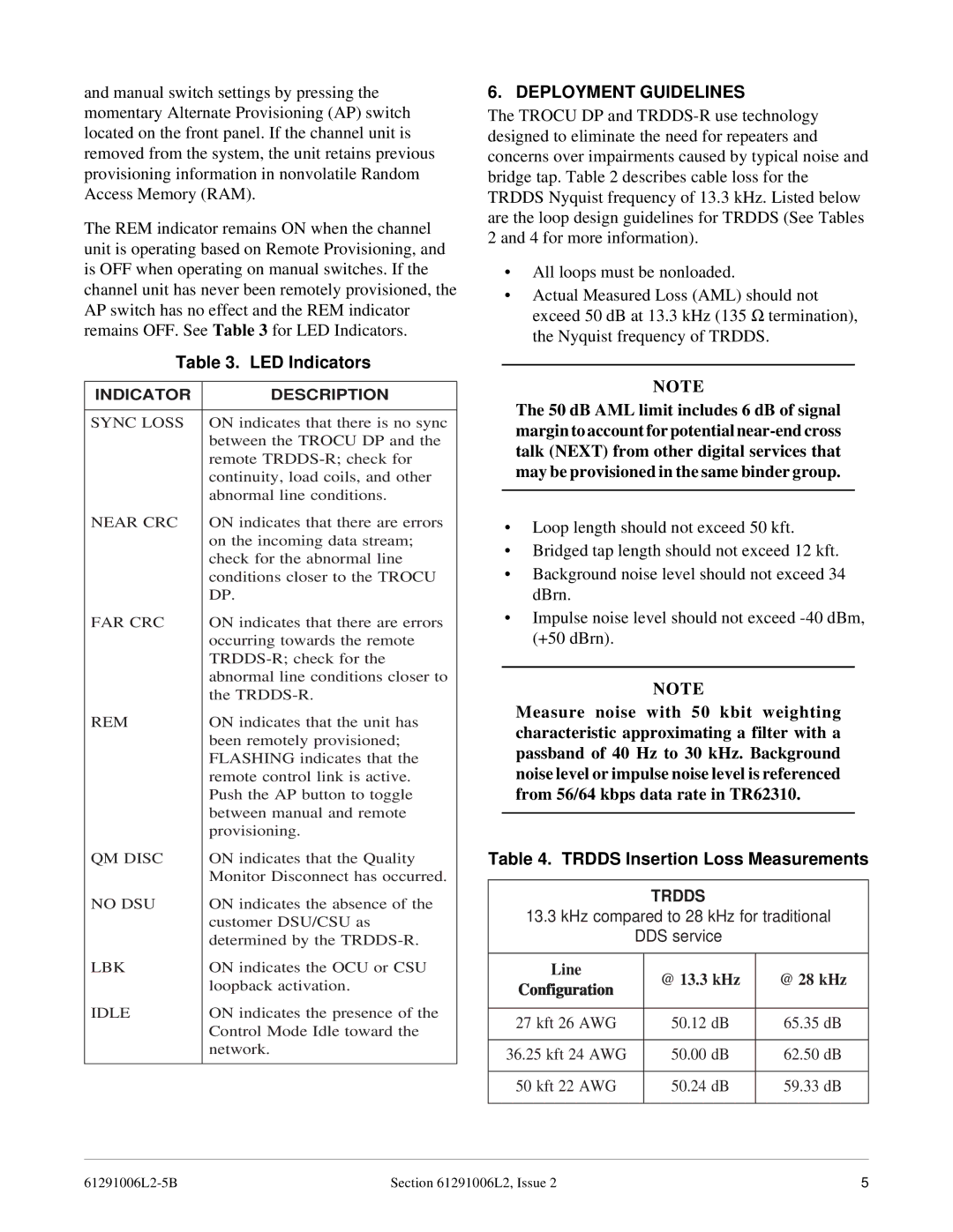
Table 3. LED Indicators
INDICATOR | DESCRIPTION |
|
|
SYNC LOSS | ON indicates that there is no sync |
| between the TROCU DP and the |
| remote |
| continuity, load coils, and other |
| abnormal line conditions. |
NEAR CRC | ON indicates that there are errors |
| on the incoming data stream; |
| check for the abnormal line |
| conditions closer to the TROCU |
| DP. |
FAR CRC | ON indicates that there are errors |
| occurring towards the remote |
| |
| abnormal line conditions closer to |
| the |
REM | ON indicates that the unit has |
| been remotely provisioned; |
| FLASHING indicates that the |
| remote control link is active. |
| Push the AP button to toggle |
| between manual and remote |
| provisioning. |
QM DISC | ON indicates that the Quality |
| Monitor Disconnect has occurred. |
NO DSU | ON indicates the absence of the |
| customer DSU/CSU as |
| determined by the |
LBK | ON indicates the OCU or CSU |
| loopback activation. |
IDLE | ON indicates the presence of the |
| Control Mode Idle toward the |
| network. |
|
|
6. DEPLOYMENT GUIDELINES
The TROCU DP and
•All loops must be nonloaded.
•Actual Measured Loss (AML) should not exceed 50 dB at 13.3 kHz (135 Ω termination),
the Nyquist frequency of TRDDS.
NOTE
The 50 dB AML limit includes 6 dB of signal margin to account for potential
•Loop length should not exceed 50 kft.
•Bridged tap length should not exceed 12 kft.
•Background noise level should not exceed 34 dBrn.
•Impulse noise level should not exceed
NOTE
Measure noise with 50 kbit weighting characteristic approximating a filter with a passband of 40 Hz to 30 kHz. Background noise level or impulse noise level is referenced from 56/64 kbps data rate in TR62310.
Table 4. TRDDS Insertion Loss Measurements
TRDDS
13.3kHz compared to 28 kHz for traditional DDS service
Line | @ 13.3 kHz | @ 28 kHz | |
Configuration | |||
|
| ||
|
|
| |
27 kft 26 AWG | 50.12 dB | 65.35 dB | |
|
|
| |
36.25 kft 24 AWG | 50.00 dB | 62.50 dB | |
|
|
| |
50 kft 22 AWG | 50.24 dB | 59.33 dB | |
|
|
|
Section 61291006L2, Issue 2 | 5 |