Section 61291006L2-5
Issue 2, June 1999
CLEI Code #D4D3MPY_ _ _
Model TROCU DP Preferred Option
Total Reach®
Installation and Maintenance
CONTENTS |
| ||
1. | GENERAL | 1 | |
2. | OPTIONS | 2 | |
3. | INSTALLATION | 3 | |
4. | TESTING | 3 | |
5. | REMOTE PROVISIONING AND |
| |
| DIAGNOSTICS | 4 | |
6. | DEPLOYMENT GUIDELINES | 5 | |
7. | WARRANTY AND CUSTOMER SERVICE | 6 | |
FIGURES |
| ||
Figure 1. TROCU DP Preferred Option | 1 | ||
Figure 2. Total Reach DDS Circuit Diagram | 1 | ||
Figure 3. | Option Switch | 2 | |
Figure 4. | Rate Selection | 2 | |
Figure 5. OCU Loopback at the TROCU DP | 4 | ||
Figure 6. TROCU DP Bidirectional Loopback |
| ||
|
|
| 4 |
Figure 7. TROCU DP Bidirectional Loopback |
| ||
|
| Normal Mode | 4 |
TABLES |
| ||
Table 1. | Preprovisioning | 3 | |
Table 2. Cable Type Loss Data @ 13.3 kHz | 3 | ||
Table 3. | LED Indicators | 5 | |
Table 4. TRDDS Insertion Loss Measurements | 5 | ||
1. GENERAL
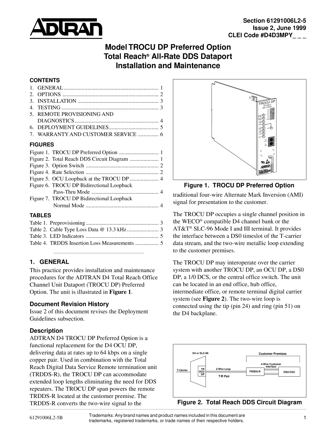
This practice provides installation and maintenance procedures for the ADTRAN D4 Total Reach Office Channel Unit Dataport (TROCU DP) Preferred Option. The unit is illustrated in Figure 1.
Document Revision History
Issue 2 of this document revises the Deployment Guidelines subsection.
Description
ADTRAN D4 TROCU DP Preferred Option is a functional replacement for the D4 OCU DP, delivering data at rates up to 64 kbps on a single copper pair. Used in combination with the Total Reach Digital Data Service Remote termination unit
SW1 |
|
|
| DP | |
TROCU |
| |
1291006L2 |
| |
SD4 |
| |
|
| |
| SC |
|
| 64 |
|
| 56 |
|
| 19.2 |
|
SYNC | 9.6 |
|
LOSS | 4.8 |
|
NEAR | 2.4 |
|
SW56 |
| |
CRC |
|
|
FAR |
|
|
CRC |
|
|
REM |
|
|
QM | AP |
|
DISC |
| |
|
| |
NO |
|
|
DSU |
|
|
LBK |
|
|
IDLE |
| L |
|
| |
Rx |
| O |
(OUT) | G | |
|
| I |
Tx |
| C |
(IN) |
| |
Figure 1. TROCU DP Preferred Option
traditional
The TROCU DP occupies a single channel position in the WECO® compatible D4 channel bank or the AT&T®
The TROCU DP may interoperate over the carrier system with another TROCU DP, an OCU DP, a DS0 DP, a 1/0 DCS, or the central office switch. The unit can be located in an end office, hub office, intermediate office, or remote terminal digital carrier system (see Figure 2). The
| D4 or | Customer Premises | ||
|
|
| ||
| TR | Interface | ||
| ||||
OCU | DSU/CSU | |||
| ||||
| DP | T/R Pair |
| |
|
|
| ||
Figure 2. Total Reach DDS Circuit Diagram
Trademarks: Any brand names and product names included in this document are | 1 | |
Section 61291006L2, Issue 2 | ||
| trademarks, registered trademarks, or trade names of their respective holders. |
|