NT1 ACE4 User Manual
Table 1-3. Local Bus Connector Pin Assignments
Pin | Description |
1No connection
2No connection
3S/T interface Receive Power Source 1 (Negative)
4S/T interface Transmit Power Source 1 (Positive)
5S/T interface Transmit Power Source 1 (Positive)
6S/T interface Receive Power Source 1 (Negative)
7No connection
8No connection
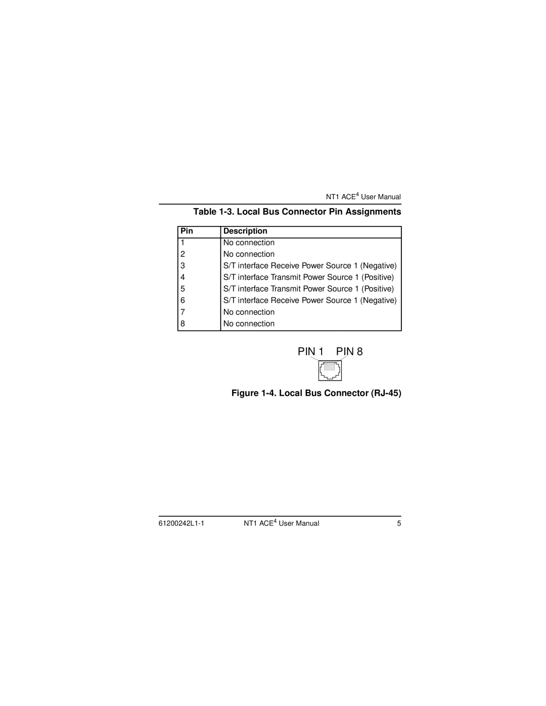
PIN 1 PIN 8
Figure 1-4. Local Bus Connector (RJ-45)
| NT1 ACE4 User Manual | 5 |