Section 61291021L5-5A
Issue 1, April 1999
CLEI Code # D4OIKTU8 _ _
TRDDS-R
Total Reach® All Rate DDS Termination Unit
For Outside Plant and Customer Premise
Installation and Maintenance
CONTENTS | |
1. | GENERAL | 1 |
2. | OPTIONS | 2 |
3. | INSTALLATION | 2 |
4. | TESTING | 4 |
5. | DEPLOYMENT GUIDELINES | 6 |
6. | WARRANTY AND CUSTOMER SERVICE | 7 |
FIGURES | | |
Figure 1. | ADTRAN TRDDS-R | 1 |
Figure 2. Total Reach DDS Circuit Diagram | 2 |
Figure 3. TRDDS-R Option Switch | 2 |
Figure 4. Circuit Card Pin Assignments | 3 |
Figure 5. Signal Loss Indication | 4 |
Figure 6. Total Reach Dataport Bidirectional Loopback | |
| | Pass-Thru Mode | 6 |
Figure 7. Total Reach Dataport Bidirectional Loopback | |
| | Normal Mode | 6 |
TABLES | | |
Table 1. | Wiring Connections | 3 |
Table 2. | UL/CUL Telecommunications Codes | 3 |
Table 3. | Faceplate Indicators | 4 |
Table 4. | TRDDS-R and Total Reach Dataport Loopback | |
| | Interoperability Matrix | 4 |
Table 5. | Latching Loopback Sequences | 5 |
Table 6. | Alternating Loopback Sequences | 5 |
Table 7. | Total Reach Dataport Loopbacks | 6 |
Table 8. | Cable Type and Temperature Loss Data | |
| | @ 13.3 kHz | 7 |
Table 9. | TRDDS Insertion Loss Measurements | 7 |
Custom
Telecom
E190349
SW 1
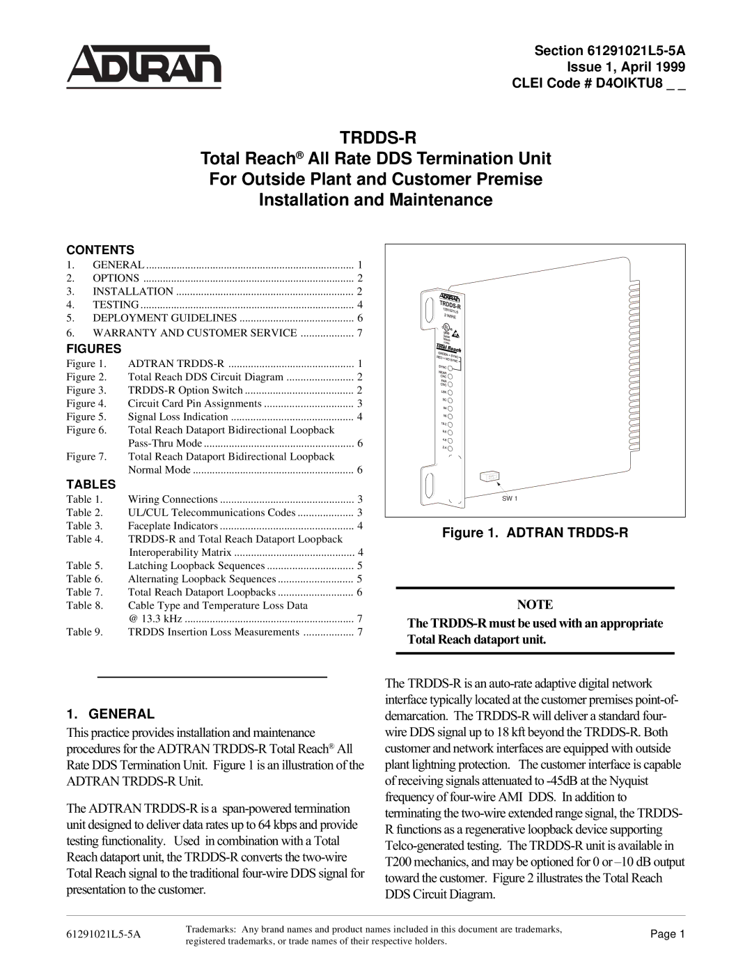
Figure 1. ADTRAN TRDDS-R
NOTE
The TRDDS-R must be used with an appropriate Total Reach dataport unit.
1. GENERAL
This practice provides installation and maintenance procedures for the ADTRAN TRDDS-R Total Reach¨ All Rate DDS Termination Unit. Figure 1 is an illustration of the ADTRAN TRDDS-R Unit.
The ADTRAN TRDDS-R is a span-powered termination unit designed to deliver data rates up to 64 kbps and provide testing functionality. Used in combination with a Total Reach dataport unit, the TRDDS-R converts the two-wire Total Reach signal to the traditional four-wire DDS signal for presentation to the customer.
The TRDDS-R is an auto-rate adaptive digital network interface typically located at the customer premises point-of- demarcation. The TRDDS-R will deliver a standard four- wire DDS signal up to 18 kft beyond the TRDDS-R. Both customer and network interfaces are equipped with outside plant lightning protection. The customer interface is capable of receiving signals attenuated to -45dB at the Nyquist frequency of four-wire AMI DDS. In addition to terminating the two-wire extended range signal, the TRDDS- R functions as a regenerative loopback device supporting Telco-generated testing. The TRDDS-R unit is available in T200 mechanics, and may be optioned for 0 or Ð10 dB output toward the customer. Figure 2 illustrates the Total Reach DDS Circuit Diagram.
Trademarks: Any brand names and product names included in this document are trademarks,
61291021L5-5ASection 61291021L5-5A, Issue 1Page 1 registered trademarks, or trade names of their respective holders.