Table 3. Faceplate Indicators
Indicator | Status | Explanation | |
|
|
| |
| ON | Unit is powered up | |
| Green | Synchronized with | |
|
| TROCU DP | |
SYNC |
|
| |
| Red | Not synchronized with | |
|
| TROCU DP; check for | |
|
| continuity, load coils, and | |
|
| other abnormal line | |
|
| conditions | |
|
|
| |
|
| Errors occured on the | |
|
| incoming data stream | |
NEAR CRC | ON | during the previous | |
second; check for | |||
|
| ||
|
| abnormal line conditions | |
|
| closer to the | |
|
|
| |
|
| Errors occured toward the | |
|
| Total Reach dataport | |
FAR CRC | ON | during the previous | |
second; check for | |||
|
| ||
|
| abnormal line conditions | |
|
| closer to the CO | |
|
|
| |
| ON | Loopback is activated | |
|
| towards network | |
LBK | Flashing | Bidirectional loopback at | |
| |||
|
| Total Reach dataport, Data | |
|
| ||
|
|
| |
SC | ON | Secondary Channel | |
|
| enabled | |
|
|
| |
64 | ON | 64 kbps data rate enabled | |
|
|
| |
56 | ON | 56 kbps data rate enabled | |
|
|
| |
19.2 | ON | 19.2 kbps data rate | |
|
| enabled | |
|
|
| |
9.6 | ON | 9.6 kbps data rate | |
|
| enabled | |
|
|
| |
4.8 | ON | 4.8 kbps data rate | |
|
| enabled | |
|
|
| |
2.4 | ON | 2.4 kbps data rate enabled | |
|
|
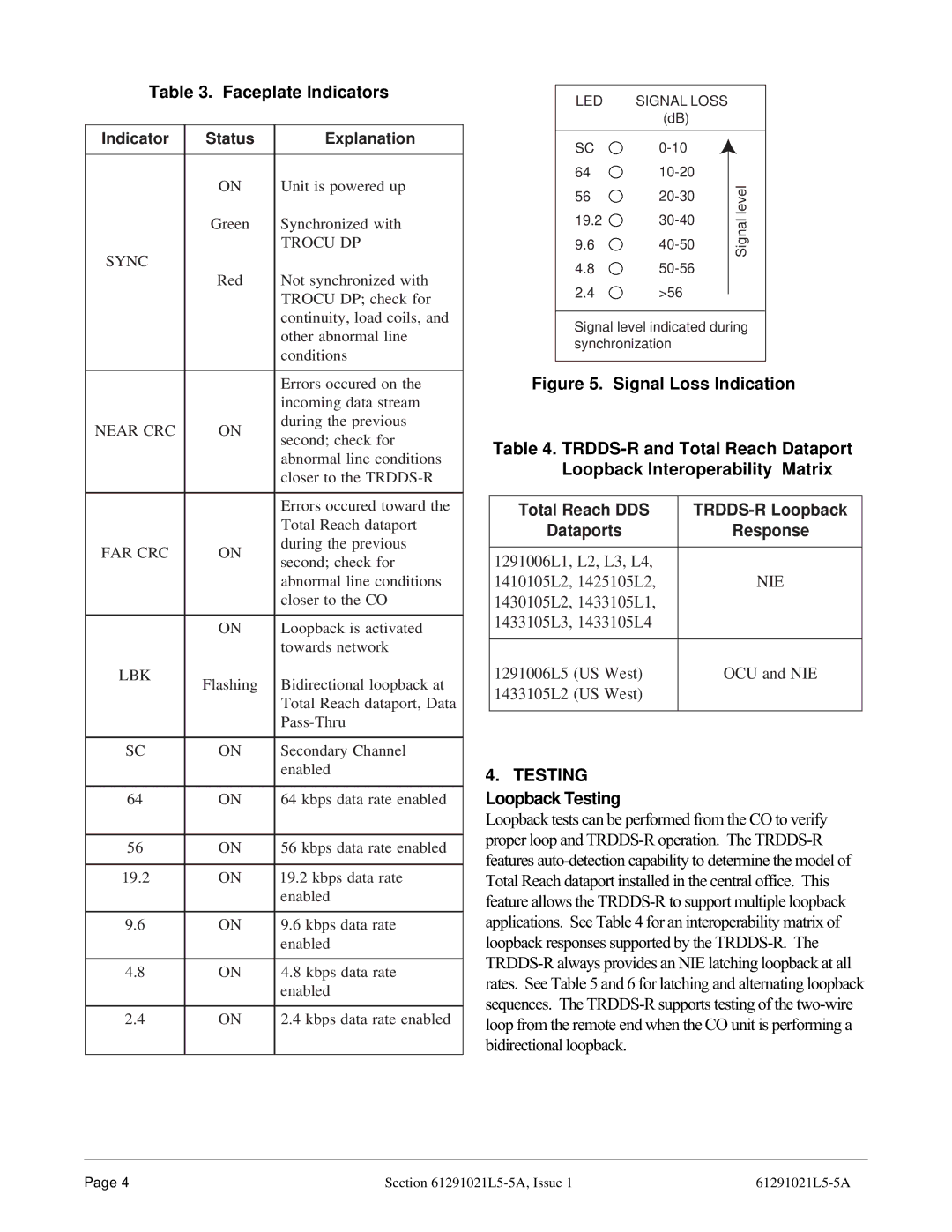
|
LED | SIGNAL LOSS |
| |
| (dB) |
| |
SC |
| ||
64 | level | ||
56 | |||
| |||
19.2 | Signal | ||
9.6 | |||
| |||
4.8 |
| ||
2.4 | >56 |
|
Signal level indicated during synchronization
Figure 5. Signal Loss Indication
Table 4.
Total Reach DDS |
|
Dataports | Response |
|
|
1291006L1, L2, L3, L4, |
|
1410105L2, 1425105L2, | NIE |
1430105L2, 1433105L1, |
|
1433105L3, 1433105L4 |
|
|
|
1291006L5 (US West) | OCU and NIE |
1433105L2 (US West) |
|
|
|
4. TESTING Loopback Testing
Loopback tests can be performed from the CO to verify proper loop and
Page 4 | Section |