Table 7. Total Reach Dataport Loopbacks
Total Reach DDS | Total Reach DDS |
Dataports | Dataport Loopbacks |
| |
1291006L1, L2, L3, L4, | |
1410105L2, 1425105L2, | OCU |
1430105L2, 1433105L1 | |
1433105L3, 1433105L4 | |
| |
1291006L5 (US West) | DS0 |
1433105L2 (US West) | |
| |
If the TRDDS-R detects a bidirectional loopback during power-up synchronization, the TRDDS-R allows data to pass on the four-wire interface by entering pass-thru mode. This permits a standard, portable DDS test set, connected to the four-wire customer interface of the TRDDS-R, to verify the integrity of the two-wire loop by transmitting a test pattern and examining the returning data for synchronization and errors. The TRDDS-R LBK indicator always flashes during a Total Reach dataport bidirectional loopback in the pass-thru mode. Refer to Figure 6 for an illustration of the bidirectional loopback pass-thru mode.
Total Reach |
Dataport |
TRDDS-R |
Test Unit |
Data |
Pass-Thru |
Bidirectional |
loopback |
Figure 6. Total Reach Dataport Bidirectional Loopback Pass-Thru Mode
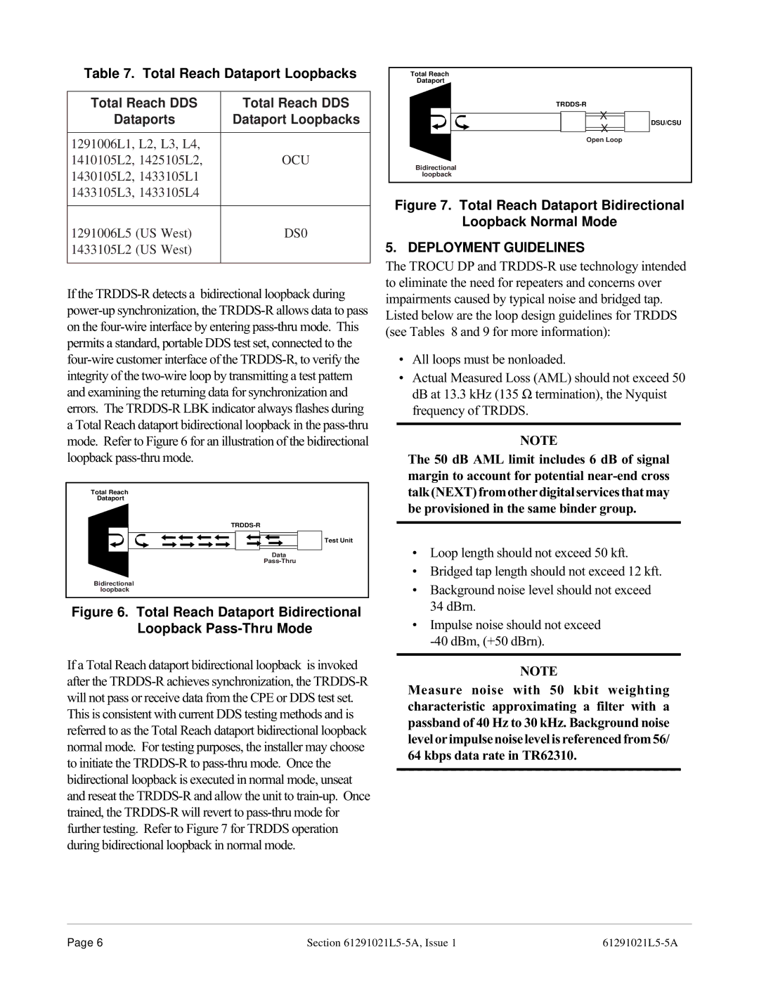
If a Total Reach dataport bidirectional loopback is invoked after the TRDDS-R achieves synchronization, the TRDDS-R will not pass or receive data from the CPE or DDS test set. This is consistent with current DDS testing methods and is referred to as the Total Reach dataport bidirectional loopback normal mode. For testing purposes, the installer may choose to initiate the TRDDS-R to pass-thru mode. Once the bidirectional loopback is executed in normal mode, unseat and reseat the TRDDS-R and allow the unit to train-up. Once trained, the TRDDS-R will revert to pass-thru mode for further testing. Refer to Figure 7 for TRDDS operation during bidirectional loopback in normal mode.
| Total Reach | |
| Dataport | |
| TRDDS-R | |
| X | DSU/CSU |
| X |
| |
| Open Loop | |
| Bidirectional | |
| loopback | |
Figure 7. Total Reach Dataport Bidirectional
Loopback Normal Mode
5. DEPLOYMENT GUIDELINES
The TROCU DP and TRDDS-R use technology intended to eliminate the need for repeaters and concerns over impairments caused by typical noise and bridged tap. Listed below are the loop design guidelines for TRDDS (see Tables 8 and 9 for more information):
¥All loops must be nonloaded.
¥Actual Measured Loss (AML) should not exceed 50 dB at 13.3 kHz (135 Ω termination), the Nyquist frequency of TRDDS.
NOTE
The 50 dB AML limit includes 6 dB of signal margin to account for potential near-end cross talk(NEXT)fromotherdigitalservicesthatmay be provisioned in the same binder group.
¥Loop length should not exceed 50 kft.
¥Bridged tap length should not exceed 12 kft.
¥Background noise level should not exceed 34 dBrn.
¥Impulse noise should not exceed -40 dBm, (+50 dBrn).
NOTE
Measure noise with 50 kbit weighting characteristic approximating a filter with a passband of 40 Hz to 30 kHz. Background noise level or impulse noise level is referenced from 56/ 64 kbps data rate in TR62310.