| Channel Bank |
|
|
|
|
|
| Customer Premises |
|
|
|
| or Outside Plant | |
|
|
|
| |
| TR |
| Interface | |
| ||||
OCU |
| DSU/CSU | ||
|
| |||
| DP | T/R Pair |
| Up to |
|
|
| ||
|
|
|
| 18 kft or |
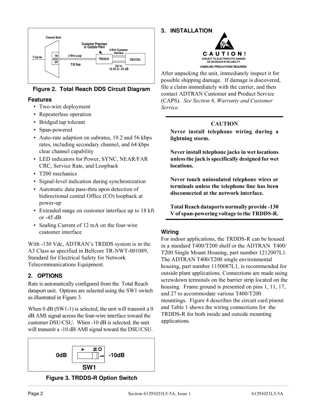
Figure 2. Total Reach DDS Circuit Diagram
Features
¥
¥Repeaterless operation
¥Bridged tap tolerant
¥
¥
¥LED indicators for Power, SYNC, NEAR/FAR CRC, Service Rate, and Loopback
¥T200 mechanics
¥
¥Automatic data
¥Extended range on customer interface up to 18 kft or
¥Sealing Current of 12 mA on the
With
2. OPTIONS
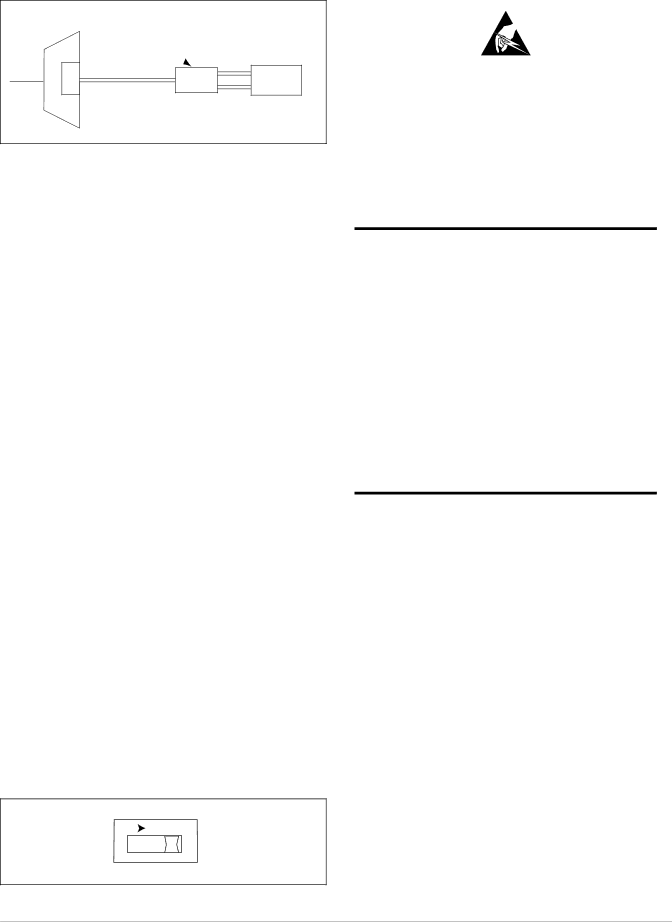
Rate is automatically configured from the Total Reach dataport unit. Options are selected using the SW1 switch as illustrated in Figure 3.
When 0 dB
0dB | N O |
|
1 |
SW1
Figure 3. TRDDS-R Option Switch
3. INSTALLATION
C A U T I O N !
SUBJECT TO ELECTROSTATIC DAMAGE
OR DECREASE IN RELIABILITY.
HANDLING PRECAUTIONS REQUIRED.
After unpacking the unit, immediately inspect it for possible shipping damage. If damage is discovered, file a claim immediately with the carrier, and then contact ADTRAN Customer and Product Service (CAPS). See Section 6, Warranty and Customer Service.
CAUTION
Never install telephone wiring during a lightning storm.
Never install telephone jacks in wet locations unless the jack is specifically designed for wet locations.
Never touch uninsulated telephone wires or terminals unless the telephone line has been disconnected at the network interface.
Total Reach dataports normally provide
Wiring
For indoor applications, the
Page 2 | Section |