4. Initial setting
4-1. EEPROM setting
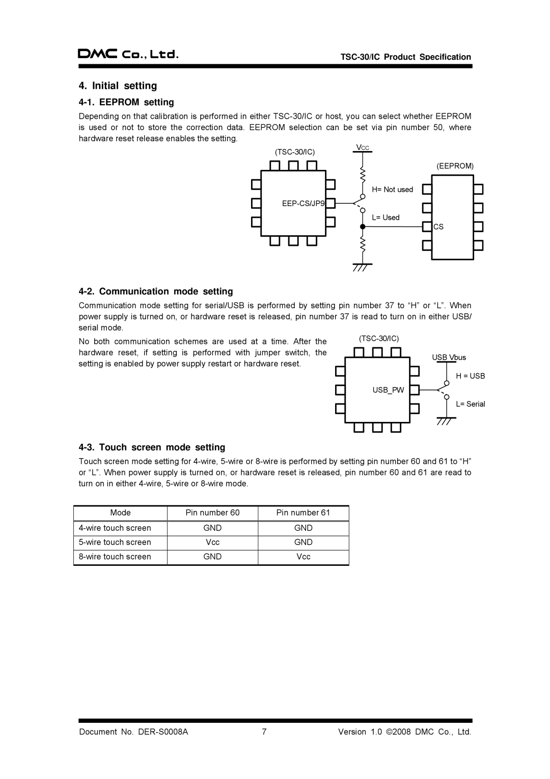
Depending on that calibration is performed in either
VCC
H= Not used
L= Used
(EEPROM)
CS
4-2. Communication mode setting
Communication mode setting for serial/USB is performed by setting pin number 37 to “H” or “L”. When power supply is turned on, or hardware reset is released, pin number 37 is read to turn on in either USB/ serial mode.
No both communication schemes are used at a time. After the hardware reset, if setting is performed with jumper switch, the setting is enabled by power supply restart or hardware reset.
USB_PW
USB Vbus
H = USB
L= Serial
4-3. Touch screen mode setting
Touch screen mode setting for
Mode | Pin number 60 | Pin number 61 |
|
|
|
GND | GND | |
|
|
|
Vcc | GND | |
|
|
|
GND | Vcc | |
|
|
|
Document No. | 7 | Version 1.0 ©2008 DMC Co., Ltd. |