Features and Functions | 3 |
Trigger Bus [0...7]
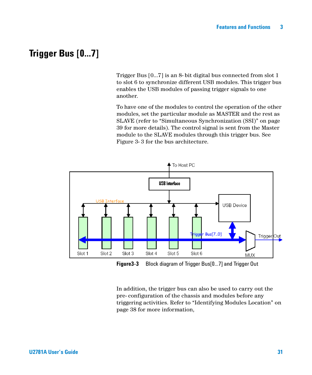
Trigger Bus [0...7] is an 8- bit digital bus connected from slot 1 to slot 6 to synchronize different USB modules. This trigger bus enables the USB modules of passing trigger signals to one another.
To have one of the modules to control the operation of the other modules, set the particular module as MASTER and the rest as SLAVE (refer to “Simultaneous Synchronization (SSI)” on page 39 for more details). The control signal is sent from the Master module to the SLAVE modules through this trigger bus. See Figure 3- 3 for the bus architecture.
Figure3-3 Block diagram of Trigger Bus[0...7] and Trigger Out
In addition, the trigger bus can also be used to carry out the pre- configuration of the chassis and modules before any triggering activities. Refer to “Identifying Modules Location” on page 38 for more information,
U2781A User’s Guide | 31 |