Aiphone IMU-100, Iai-100, IME-100, IME-150, ISE-100, IAX-100 operation manual 10mm

Models: IME-150 ISE-100 IAX-100 IME-100 IMU-100 Iai-100

1 20
Download 20 pages 8.26 Kb
Page 10
Image 10

4-8

Guideline

[1]


[2]

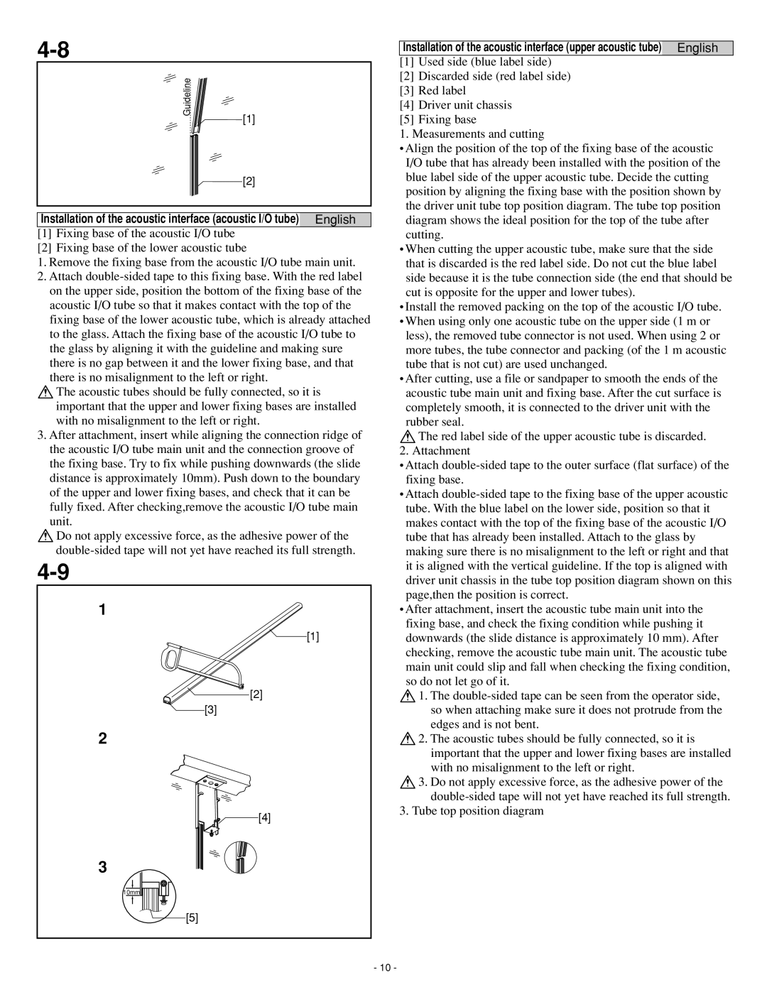
Installation of the acoustic interface (acoustic I/O tube) English

[1]Fixing base of the acoustic I/O tube

[2]Fixing base of the lower acoustic tube

1. Remove the fixing base from the acoustic I/O tube main unit.

2. Attach double-sided tape to this fixing base. With the red label on the upper side, position the bottom of the fixing base of the acoustic I/O tube so that it makes contact with the top of the fixing base of the lower acoustic tube, which is already attached to the glass. Attach the fixing base of the acoustic I/O tube to the glass by aligning it with the guideline and making sure there is no gap between it and the lower fixing base, and that there is no misalignment to the left or right.

The acoustic tubes should be fully connected, so it is important that the upper and lower fixing bases are installed with no misalignment to the left or right.

3. After attachment, insert while aligning the connection ridge of the acoustic I/O tube main unit and the connection groove of the fixing base. Try to fix while pushing downwards (the slide distance is approximately 10mm). Push down to the boundary of the upper and lower fixing bases, and check that it can be fully fixed. After checking,remove the acoustic I/O tube main unit.

Do not apply excessive force, as the adhesive power of the double-sided tape will not yet have reached its full strength.

4-9

1

[1]

[2]

[3]

2

[4]

3

10mm

[5]

Installation of the acoustic interface (upper acoustic tube) English

[1]Used side (blue label side)

[2]Discarded side (red label side)

[3]Red label

[4]Driver unit chassis

[5]Fixing base

1. Measurements and cutting

Align the position of the top of the fixing base of the acoustic I/O tube that has already been installed with the position of the blue label side of the upper acoustic tube. Decide the cutting position by aligning the fixing base with the position shown by the driver unit tube top position diagram. The tube top position diagram shows the ideal position for the top of the tube after cutting.

When cutting the upper acoustic tube, make sure that the side that is discarded is the red label side. Do not cut the blue label side because it is the tube connection side (the end that should be cut is opposite for the upper and lower tubes).

Install the removed packing on the top of the acoustic I/O tube.

When using only one acoustic tube on the upper side (1 m or less), the removed tube connector is not used. When using 2 or more tubes, the tube connector and packing (of the 1 m acoustic tube that is not cut) are used unchanged.

After cutting, use a file or sandpaper to smooth the ends of the acoustic tube main unit and fixing base. After the cut surface is completely smooth, it is connected to the driver unit with the rubber seal.

The red label side of the upper acoustic tube is discarded. 2. Attachment

Attach double-sided tape to the outer surface (flat surface) of the fixing base.

Attach double-sided tape to the fixing base of the upper acoustic tube. With the blue label on the lower side, position so that it makes contact with the top of the fixing base of the acoustic I/O tube that has already been installed. Attach to the glass by making sure there is no misalignment to the left or right and that it is aligned with the vertical guideline. If the top is aligned with driver unit chassis in the tube top position diagram shown on this page,then the position is correct.

After attachment, insert the acoustic tube main unit into the fixing base, and check the fixing condition while pushing it downwards (the slide distance is approximately 10 mm). After checking, remove the acoustic tube main unit. The acoustic tube main unit could slip and fall when checking the fixing condition, so do not let go of it.

1. The double-sided tape can be seen from the operator side, so when attaching make sure it does not protrude from the edges and is not bent.

2. The acoustic tubes should be fully connected, so it is important that the upper and lower fixing bases are installed with no misalignment to the left or right.

3. Do not apply excessive force, as the adhesive power of the double-sided tape will not yet have reached its full strength.

3. Tube top position diagram

- 10 -

Page 10
Image 10
Aiphone IMU-100, Iai-100, IME-100, IME-150, ISE-100, IAX-100 operation manual 10mm

IME-150, ISE-100, IAX-100, IME-100, IMU-100 specifications

Aiphone, a leading manufacturer of intercom and security communication systems, has developed a range of products designed for different needs and environments. Among their notable offerings are the IAI-100, IME-100, IMU-100, IAX-100, and ISE-100 models. Each device comes with unique features, advanced technologies, and specific characteristics suited for various applications.

The Aiphone IAI-100 serves as a powerful intercom system that is ideal for businesses and residential settings. It features a high-resolution display that allows for clear video communication. The IAI-100 utilizes advanced networking technologies, such as IP connectivity, enabling seamless integration into existing networks. With its user-friendly interface, users can easily navigate through functions, making communication efficient. Additionally, its robust security features ensure that conversations are private and protected from unauthorized access.

The IME-100 model is designed for enhanced communication in environments requiring reliability and durability. It incorporates a weather-resistant design, making it suitable for outdoor installations. The IME-100 also supports two-way audio and video communication, providing users with a comprehensive solution for monitoring entry points. Its advanced motion detection technology alerts users to any movement, ensuring proactive security measures.

The IMU-100 offers a versatile solution for both audio and video intercom needs. This unit stands out with its ability to connect multiple devices, allowing for the management of several communication channels simultaneously. Its integration with mobile applications enables users to access their intercom system remotely, offering convenience and control. The IMU-100 also supports high-definition video, ensuring clear visuals for identification and communication purposes.

The IAX-100 model is focused on integrating access control with intercom functionalities. This unit allows users to grant or deny access to visitors through a single interface. It features a built-in access control panel and is compatible with various locking mechanisms, making it a comprehensive solution for commercial buildings. The IAX-100 also provides detailed logging of entry attempts, enhancing security oversight.

Lastly, the ISE-100 is designed specifically for education and institutional applications. It features an easy-to-use interface tailored to the needs of school environments, supporting quick communication between teachers, staff, and administration. The ISE-100 also has features such as emergency notification systems and integration with classroom technology, ensuring safety and communication efficiency.

In summary, Aiphone's IAI-100, IME-100, IMU-100, IAX-100, and ISE-100 models are expertly crafted to meet varying communication and security needs across different settings. Each device emphasizes innovative technologies, user-friendly interfaces, and robust security features, making them valuable tools for enhancing connectivity and safety.