IME-150, ISE-100, IAX-100, IME-100, IMU-100 specifications
Aiphone, a leading manufacturer of intercom and security communication systems, has developed a range of products designed for different needs and environments. Among their notable offerings are the IAI-100, IME-100, IMU-100, IAX-100, and ISE-100 models. Each device comes with unique features, advanced technologies, and specific characteristics suited for various applications.The Aiphone IAI-100 serves as a powerful intercom system that is ideal for businesses and residential settings. It features a high-resolution display that allows for clear video communication. The IAI-100 utilizes advanced networking technologies, such as IP connectivity, enabling seamless integration into existing networks. With its user-friendly interface, users can easily navigate through functions, making communication efficient. Additionally, its robust security features ensure that conversations are private and protected from unauthorized access.
The IME-100 model is designed for enhanced communication in environments requiring reliability and durability. It incorporates a weather-resistant design, making it suitable for outdoor installations. The IME-100 also supports two-way audio and video communication, providing users with a comprehensive solution for monitoring entry points. Its advanced motion detection technology alerts users to any movement, ensuring proactive security measures.
The IMU-100 offers a versatile solution for both audio and video intercom needs. This unit stands out with its ability to connect multiple devices, allowing for the management of several communication channels simultaneously. Its integration with mobile applications enables users to access their intercom system remotely, offering convenience and control. The IMU-100 also supports high-definition video, ensuring clear visuals for identification and communication purposes.
The IAX-100 model is focused on integrating access control with intercom functionalities. This unit allows users to grant or deny access to visitors through a single interface. It features a built-in access control panel and is compatible with various locking mechanisms, making it a comprehensive solution for commercial buildings. The IAX-100 also provides detailed logging of entry attempts, enhancing security oversight.
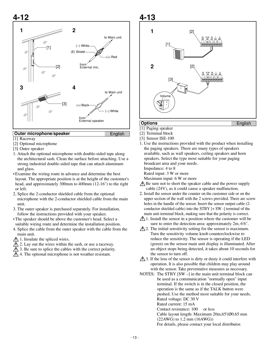
Lastly, the ISE-100 is designed specifically for education and institutional applications. It features an easy-to-use interface tailored to the needs of school environments, supporting quick communication between teachers, staff, and administration. The ISE-100 also has features such as emergency notification systems and integration with classroom technology, ensuring safety and communication efficiency.
In summary, Aiphone's IAI-100, IME-100, IMU-100, IAX-100, and ISE-100 models are expertly crafted to meet varying communication and security needs across different settings. Each device emphasizes innovative technologies, user-friendly interfaces, and robust security features, making them valuable tools for enhancing connectivity and safety.

