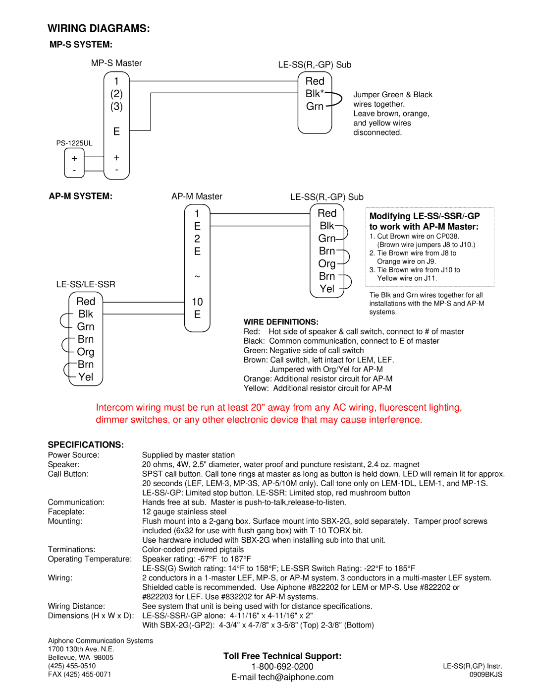
LE-SS/LE-SSR/LE-SS-GP, LE-SS specifications
Aiphone is renowned for its high-quality intercom and communication systems, and the Aiphone A series continues this legacy with models like the LE-SS and LE-SS/LE-SSR. These systems are designed for both residential and commercial applications, offering users seamless communication and security solutions.The Aiphone LE-SS is a sleek and compact intercom system that enhances user convenience and safety. Notably, it features a robust construction with a weather-resistant design, making it suitable for both indoor and outdoor installations. This ensures that the system remains operational under various environmental conditions.
One of the primary features of the Aiphone LE-SS is its two-way audio communication. Users can easily converse with visitors without the need to open their doors. This provides an added layer of security, allowing users to screen visitors effectively. The intercom system utilizes advanced microphone and speaker technology, ensuring clear and noise-free communication.
Another standout feature of the LE-SS is its video functionality. The LE-SS model is equipped with a high-resolution camera that captures clear images of visitors. This video support allows users to verify the identity of guests before granting access, significantly enhancing security.
The LE-SS/LE-SSR model expands on the functionality of the LE-SS by incorporating additional features such as a built-in monitor. This monitor displays real-time video feeds from the entryway camera, enabling users to see who is at the door directly. The LE-SSR version includes enhanced features for larger installations, accommodating multiple camera inputs and additional intercom stations throughout the property.
Both the LE-SS and LE-SS/LE-SSR incorporate advanced digital technologies, ensuring reliable operation and minimal interference. They support a range of communication protocols, allowing integration with other security systems and technologies. This interoperability expands the possibilities for users looking to create a comprehensive security ecosystem.
In conclusion, the Aiphone LE-SS and LE-SS/LE-SSR intercom systems provide innovative solutions for modern communication and security needs. With their robust design, two-way audio communication, high-resolution video capabilities, and advanced digital technologies, these systems ensure safety and convenience for users in diverse settings. Whether used in a residential context or as part of a commercial security framework, Aiphone continues to set a high standard in intercom solutions.

