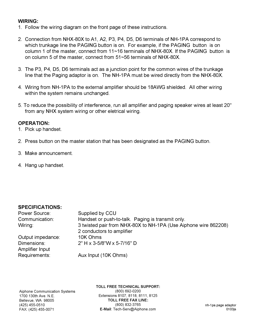
NH-1PA specifications
The Aiphone NH-1PA is a sophisticated intercom and communication device designed to meet the growing demands for effective communication in various environments, including residential homes, offices, and commercial spaces. This advanced intercom system offers a range of features and technologies that enhance connectivity and convenience.One of the standout features of the NH-1PA is its high-definition audio quality. The device utilizes advanced audio processing technology to ensure crystal-clear audio during conversations. This clarity is crucial in environments where clear communication is essential, such as in busy offices or homes with multiple rooms.
The NH-1PA is designed with user-friendly controls, making it easy for anyone to operate. Its intuitive interface allows users to access various functions quickly, such as adjusting volume, accessing the door release feature, and switching between different intercom stations. This ease of use is particularly beneficial for households with children or elderly members.
Another significant characteristic of the NH-1PA is its superior connectivity options. The device supports both wired and wireless connections, allowing for flexible installation according to the layout and specific needs of any space. Additionally, the NH-1PA can be integrated with other Aiphone systems, offering scalability for larger installations.
The intercom is also equipped with a video feature, providing users with visual confirmation before granting access to visitors. This feature increases security and peace of mind, as users can see who is at the door. The high-resolution video display ensures clear images, even in low-light conditions.
The NH-1PA is built to last, featuring a robust and durable design that can withstand the rigors of daily use. It is also designed for easy installation, which can be accomplished without extensive technical knowledge. The device comes with a comprehensive user manual and installation guide, making the setup process straightforward.
In addition to its core functionalities, the NH-1PA includes advanced features such as Do Not Disturb mode, message recording capabilities, and bell functionality that can be integrated with other smart home systems.
Overall, the Aiphone NH-1PA is a modern intercom solution that combines audio and video communication capabilities with advanced features and easy installation. Its durability and high-quality performance make it a valuable addition to any home or business looking to enhance communication and security.
