IMPORTANT INSTRUCTIONS - OPERATING MANUAL

CEILING MOUNT INSTALLATION (Figures 1 and 2)

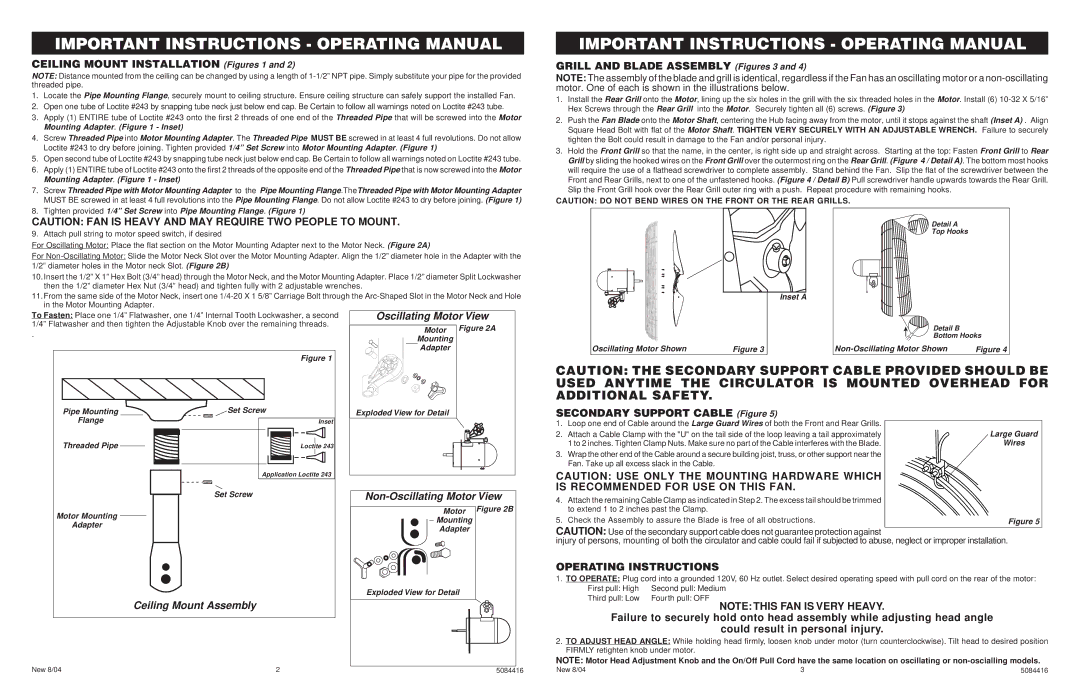
NOTE: Distance mounted from the ceiling can be changed by using a length of 1-1/2” NPT pipe. Simply substitute your pipe for the provided threaded pipe.

1.Locate the Pipe Mounting Flange, securely mount to ceiling structure. Ensure ceiling structure can safely support the installed Fan.

2.Open one tube of Loctite #243 by snapping tube neck just below end cap. Be Certain to follow all warnings noted on Loctite #243 tube.

3.Apply (1) ENTIRE tube of Loctite #243 onto the first 2 threads of one end of the Threaded Pipe that will be screwed into the Motor Mounting Adapter. (Figure 1 - Inset)

4.Screw Threaded Pipe into Motor Mounting Adapter. The Threaded Pipe MUST BE screwed in at least 4 full revolutions. Do not allow Loctite #243 to dry before joining. Tighten provided 1/4” Set Screw into Motor Mounting Adapter. (Figure 1)

5.Open second tube of Loctite #243 by snapping tube neck just below end cap. Be Certain to follow all warnings noted on Loctite #243 tube.

6.Apply (1) ENTIRE tube of Loctite #243 onto the first 2 threads of the opposite end of the Threaded Pipe that is now screwed into the Motor Mounting Adapter. (Figure 1 - Inset)

7.Screw Threaded Pipe with Motor Mounting Adapter to the Pipe Mounting Flange.TheThreaded Pipe with Motor Mounting Adapter MUST BE screwed in at least 4 full revolutions into the Pipe Mounting Flange. Do not allow Loctite #243 to dry before joining. (Figure 1)

8.Tighten provided 1/4” Set Screw into Pipe Mounting Flange. (Figure 1)

IMPORTANT INSTRUCTIONS - OPERATING MANUAL

GRILL AND BLADE ASSEMBLY (Figures 3 and 4)

NOTE: The assembly of the blade and grill is identical, regardless if the Fan has an oscillating motor or a non-oscillating motor. One of each is shown in the illustrations below.

1.Install the Rear Grill onto the Motor, lining up the six holes in the grill with the six threaded holes in the Motor. Install (6) 10-32 X 5/16” Hex Screws through the Rear Grill into the Motor. Securely tighten all (6) screws. (Figure 3)

2.Push the Fan Blade onto the Motor Shaft, centering the Hub facing away from the motor, until it stops against the shaft (Inset A) . Align Square Head Bolt with flat of the Motor Shaft. TIGHTEN VERY SECURELY WITH AN ADJUSTABLE WRENCH. Failure to securely tighten the Bolt could result in damage to the Fan and/or personal injury.

3.Hold the Front Grill so that the name, in the center, is right side up and straight across. Starting at the top: Fasten Front Grill to Rear Grill by sliding the hooked wires on the Front Grill over the outermost ring on the Rear Grill. (Figure 4 / Detail A). The bottom most hooks will require the use of a flathead screwdriver to complete assembly. Stand behind the Fan. Slip the flat of the screwdriver between the Front and Rear Grills, next to one of the unfastened hooks. (Figure 4 / Detail B) Pull screwdriver handle upwards towards the Rear Grill. Slip the Front Grill hook over the Rear Grill outer ring with a push. Repeat procedure with remaining hooks.

CAUTION: DO NOT BEND WIRES ON THE FRONT OR THE REAR GRILLS.

CAUTION: FAN IS HEAVY AND MAY REQUIRE TWO PEOPLE TO MOUNT.

9. Attach pull string to motor speed switch, if desired

For Oscillating Motor: Place the flat section on the Motor Mounting Adapter next to the Motor Neck. (Figure 2A)

For Non-Oscillating Motor: Slide the Motor Neck Slot over the Motor Mounting Adapter. Align the 1/2” diameter hole in the Adapter with the 1/2” diameter holes in the Motor neck Slot. (Figure 2B)

10.Insert the 1/2” X 1” Hex Bolt (3/4” head) through the Motor Neck, and the Motor Mounting Adapter. Place 1/2” diameter Split Lockwasher then the 1/2” diameter Hex Nut (3/4” head) and tighten fully with 2 adjustable wrenches.

11.From the same side of the Motor Neck, insert one 1/4-20 X 1 5/8” Carriage Bolt through the Arc-Shaped Slot in the Motor Neck and Hole in the Motor Mounting Adapter.

To Fasten: Place one 1/4” Flatwasher, one 1/4” Internal Tooth Lockwasher, a second

Oscillating Motor View

1/4” Flatwasher and then tighten the Adjustable Knob over the remaining threads.

Motor

Figure 2A

.

Mounting


Adapter


Figure 1


Oscillating Motor Shown

Figure 3

Inset A

Detail A

Top Hooks

Detail B

Bottom Hooks

Non-Oscillating Motor Shown

Figure 4

Pipe Mounting

Set Screw

Exploded View for Detail

Flange


Inset

Threaded Pipe


Loctite 243


Application Loctite 243


Set Screw

Non-Oscillating Motor View

Motor Mounting


Motor Figure 2B


Mounting

Adapter


Adapter


Exploded View for Detail


Ceiling Mount Assembly


New 8/04

2

5084416

CAUTION: THE SECONDARY SUPPORT CABLE PROVIDED SHOULD BE USED ANYTIME THE CIRCULATOR IS MOUNTED OVERHEAD FOR ADDITIONAL SAFETY.

SECONDARY SUPPORT CABLE (Figure 5)

1. Loop one end of Cable around the Large Guard Wires of both the Front and Rear Grills.

2.

Attach a Cable Clamp with the "U" on the tail side of the loop leaving a tail approximately

Large Guard


1 to 2 inches. Tighten Clamp Nuts. Make sure no part of the Cable interferes with the Blade.

Wires

3.

Wrap the other end of the Cable around a secure building joist, truss, or other support near the


Fan. Take up all excess slack in the Cable.


CAUTION: USE ONLY THE MOUNTING HARDWARE WHICH

IS RECOMMENDED FOR USE ON THIS FAN.

4.Attach the remaining Cable Clamp as indicated in Step 2. The excess tail should be trimmed to extend 1 to 2 inches past the Clamp.

5. Check the Assembly to assure the Blade is free of all obstructions.

Figure 5

CAUTION: Use of the secondary support cable does not guarantee protection against

injury of persons, mounting of both the circulator and cable could fail if subjected to abuse, neglect or improper installation.

OPERATING INSTRUCTIONS

1. TO OPERATE: Plug cord into a grounded 120V, 60 Hz outlet. Select desired operating speed with pull cord on the rear of the motor:

First pull: High

Second pull: Medium

Third pull: Low

Fourth pull: OFF

NOTE: THIS FAN IS VERY HEAVY.

Failure to securely hold onto head assembly while adjusting head angle

could result in personal injury.

2.TO ADJUST HEAD ANGLE: While holding head firmly, loosen knob under motor (turn counterclockwise). Tilt head to desired position FIRMLY retighten knob under motor.

NOTE: Motor Head Adjustment Knob and the On/Off Pull Cord have the same location on oscillating or non-oscialling models.

New 8/04

3

5084416

Page 2
Image 2
Air King 9324, 9375, 9724, 9374 Non-Oscillating Motor View, Ceiling Mount Assembly, Is Recommended for USE on this FAN

9370, 9371, 9724, 9324, 9330 specifications

Air King has gained a reputation for producing reliable, high-performance range hoods, and their models 9374, 9371, 9375, 9724, and 9335 are exemplary of the brand’s commitment to innovation and quality in kitchen ventilation. Each model offers a unique blend of features, technologies, and characteristics that make them suitable for various cooking environments and styles.

The Air King 9374 is a wall-mounted range hood that boasts a powerful 600 CFM motor, ensuring effective removal of smoke, grease, and odors from the kitchen. Its stainless steel construction provides durability while the sleek design adds a modern touch to any kitchen décor. The unit features a three-speed blower control, allowing users to adjust the ventilation power according to their cooking needs.

Similarly, the Air King 9371 is designed with efficiency in mind. This under-cabinet model offers a slightly lower CFM rating but maintains a strong airflow capacity, effectively cleaning the air while remaining whisper-quiet. With its easy-to-clean filter and simple installation process, the 9371 caters to homeowners looking for practicality without compromising on performance.

The Air King 9375 takes versatility to the next level. This model can be used for both ducted and ductless installations, making it an excellent option for homes where ductwork is not feasible. It features an energy-efficient LED lighting system, providing ample illumination for cooking tasks while reducing energy consumption.

The 9724 model stands out due to its user-friendly interface and advanced technology. Its electronic push-button controls allow for easy operation, and it is equipped with a built-in timer, which enhances convenience for busy cooks. With its chic design, the 9724 is as stylish as it is functional, making it a perfect fit for contemporary kitchens.

Lastly, the Air King 9335 model is renowned for its robust construction and high performance. This range hood offers adjustable chimney extensions to fit various ceiling heights, ensuring a perfect fit. Additionally, its washable aluminum filters effectively capture cooking particulates, contributing to a cleaner kitchen environment.

In summary, Air King’s models 9374, 9371, 9375, 9724, and 9335 bring innovation, style, and efficiency to kitchen ventilation. From powerful motors and energy-efficient lights to versatile installation options and user-friendly controls, these range hoods are designed to meet diverse cooking needs while elevating the overall kitchen experience. Whether you are an avid home chef or a casual cook, Air King's offerings provide the functionality and performance necessary for a clean and enjoyable cooking space.