| | | | | 20" I-BEAM MOUNT FAN |
| | | | | 20" (50.8 cm) MODEL 9520 |
| | | READ AND SAVE THESE INSTRUCTIONS |
| READ CAREFULLY BEFORE ATTEMPTING TO ASSEMBLE, INSTALL, OPERATE OR MAINTAIN THE PRODUCT DESCRIBED. PROTECT YOUR- |
| | SELF AND OTHERS BY OBSERVING ALL SAFETY INFORMATION. FAILURE TO COMPLY WITH |
| | INSTRUCTIONS COULD RESULT IN PERSONAL INJURY AND/OR PROPERTY DAMAGE! |
| DESCRIPTION | | RETAIN INSTRUCTIONS FOR FUTURE REFERENCE. |
| | | 9. This Fan is not suitable for use in hazardous locations. Please refer to |
| The Air King® 20" (50.8 cm) I-Beam mount fan features 3-speed pull cord |
| operation and a 3-paddle fan blade. This fan has a permanently lubricated | | National Electric Code (NEC) Article 500 or applicable state or local |
| | codes or standards relating to electrical requirements for Hazardous |
| motor with a 9 ft. (2.74 m) 18/3 cord set and is constructed of sturdy, | |
| | locations. THIS FAN DOES NOT MEET THE REQUIRMENTS OF |
| powder coated steel. | | | | |
| | | | | NEC ARTICLE 500 (2002). |
| SPECIFICATIONS | | | |
| | | | | |
| Motor ...................................... 120 V, 50/60 Hz | | | Commerical Style Fan |
| Blade diameter ........................ 20" (50.8 cm) Model 9520 | | WARNING: This fan should be used only in a clean, dry |
| Speeds .................................... 3 | | | environment. Mounting of this product in any way other then |
| Control ..................................... Pull Cord | | | specified in the instruction sheet will null and void the |
| Air flow distribution .................. 360° | | | manufacturer's warranty. |
| Approvals................................. UL/ETL Listed. Close mesh fan guard | | | |
| | | meets OSHA requirements | WARNING: BECAUSE OF SIZE AND WEIGHT OF THIS FAN, MAKE |
| MODEL | | 9520 | |
| | | SURE ALL PARTS ARE COMPLETELY ASSEMBLED ACCORDINGTO |
| SPEED | HIGH | MED | LOW |
| INSTRUCTIONS.FAILURETO DO SO COULD RESULT IN FAN COMING |
| CFM | 7510 | 5010 | 3735 | APART DURING OPERATION AND/OR PERSONAL INJURY. |
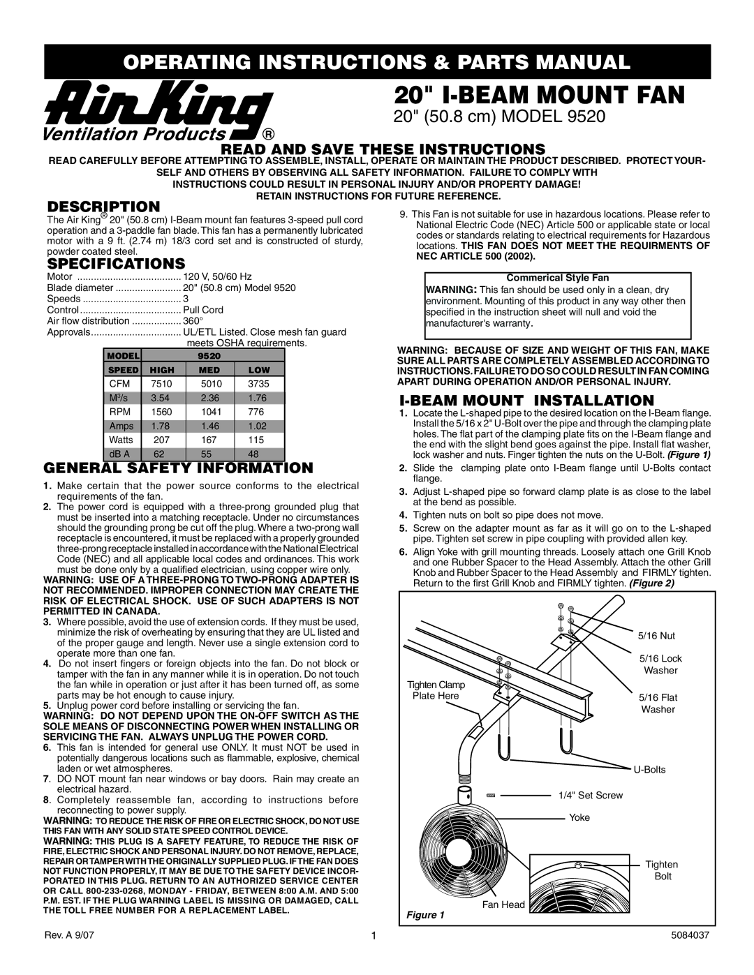
| M3/s | 3.54 | 2.36 | 1.76 | I-BEAM MOUNT INSTALLATION |
| | | |
| RPM | 1560 | 1041 | 776 | 1. Locate the L-shaped pipe to the desired location on the I-Beam flange. |
| Amps | 1.78 | 1.46 | 1.02 | | Install the 5/16 x 2" U-Bolt over the pipe and through the clamping plate |
| Watts | 207 | 167 | 115 | | holes. The flat part of the clamping plate fits on the I-Beam flange and |
| | the end with the slight bend goes against the pipe. Install flat washer, |
| dB A | 62 | 55 | 48 | |
| | lock washer and nuts. Finger tighten the nuts on the U-Bolt. (Figure 1) |
| GENERAL SAFETY INFORMATION | 2. | Slide the | clamping plate onto I-Beam flange until U-Bolts contact |
| 1. Make certain that the power source conforms to the electrical | | flange. | |
| 3. Adjust L-shaped pipe so forward clamp plate is as close to the label |
| requirements of the fan. | | |
| | | | at the bend as possible. |
| 2. The power cord is equipped with a three-prong grounded plug that | |
| 4. | Tighten nuts on bolt so pipe does not move. |
| must be inserted into a matching receptacle. Under no circumstances |
| should the grounding prong be cut off the plug. Where a two-prong wall | 5. | Screw on the adapter mount as far as it will go on to the L-shaped |
| receptacle is encountered, it must be replaced with a properly grounded | | pipe. Tighten set screw in pipe coupling with provided allen key. |
| three-prong receptacle installed in accordance with the National Electrical | 6. | Align Yoke with grill mounting threads. Loosely attach one Grill Knob |
| Code (NEC) and all applicable local codes and ordinances. This work |
| | and one Rubber Spacer to the Head Assembly. Attach the other Grill |
| must be done only by a qualified electrician, using copper wire only. | |
| | Knob and Rubber Spacer to the Head Assembly and FIRMLY tighten. |
| WARNING: USE OF A THREE-PRONG TO TWO-PRONG ADAPTER IS | |
| | Return to the first Grill Knob and FIRMLY tighten. (Figure 2) |
| NOT RECOMMENDED. IMPROPER CONNECTION MAY CREATE THE | |
| | | |
| RISK OF ELECTRICAL SHOCK. USE OF SUCH ADAPTERS IS NOT | | | |
| PERMITTED IN CANADA. | | | | | |
| 3. Where possible, avoid the use of extension cords. If they must be used, | | | |
| minimize the risk of overheating by ensuring that they are UL listed and | | | 5/16 Nut |
| of the proper gauge and length. Never use a single extension cord to | | |
| | | |
| operate more than one fan. | | | | | 5/16 Lock |
| 4. Do not insert fingers or foreign objects into the fan. Do not block or | | |
| | | Washer |
| tamper with the fan in any manner while it is in operation. Do not touch | | |
| | | |
| the fan while in operation or just after it has been turned off, as some | Tighten Clamp |
| parts may be hot enough to cause injury. | | | Plate Here | 5/16 Flat |
| 5. Unplug power cord before installing or servicing the fan. | | | Washer |
| WARNING: DO NOT DEPEND UPON THE ON-OFF SWITCH AS THE | | |
| | | |
| SOLE MEANS OF DISCONNECTING POWER WHEN INSTALLING OR | | | |
| SERVICING THE FAN. ALWAYS UNPLUG THE POWER CORD. | | | |
| 6. This fan is intended for general use ONLY. It must NOT be used in | | | |
| potentially dangerous locations such as flammable, explosive, chemical | | | |
| laden or wet atmospheres. | | | | | U-Bolts |
| 7. DO NOT mount fan near windows or bay doors. Rain may create an | | | |
| electrical hazard. | | | | | | 1/4" Set Screw |
| 8. Completely reassemble fan, according to instructions before | | |
| | | |
| reconnecting to power supply. | | | | | Yoke |
| WARNING: TO REDUCE THE RISK OF FIRE OR ELECTRIC SHOCK, DO NOT USE | | |
| | | |
| THIS FAN WITH ANY SOLID STATE SPEED CONTROL DEVICE. | | | |
| WARNING: THIS PLUG IS A SAFETY FEATURE, TO REDUCE THE RISK OF | | | |
| FIRE, ELECTRIC SHOCK AND PERSONAL INJURY. DO NOT REMOVE, REPLACE, | | | |
| REPAIR ORTAMPERWITHTHE ORIGINALLY SUPPLIED PLUG. IFTHE FAN DOES | | | Tighten |
| NOT FUNCTION PROPERLY, IT MAY BE DUE TO THE SAFETY DEVICE INCOR- | | |
| | | Bolt |
| PORATED IN THIS PLUG. RETURN TO AN AUTHORIZED SERVICE CENTER | | |
| | | |
| OR CALL 800-233-0268, MONDAY - FRIDAY, BETWEEN 8:00 A.M. AND 5:00 | | | |
| P.M. EST. IF THE PLUG WARNING LABEL IS MISSING OR DAMAGED, CALL | | | Fan Head |
| THE TOLL FREE NUMBER FOR A REPLACEMENT LABEL. | Figure 1 |
| |
| | | | | |
| Rev. A 9/07 | | | 1 | | | 5084037 |