DRLC107 specifications
The Air King DRLC107 is a standout among kitchen range hoods, designed to provide powerful ventilation while enhancing the overall aesthetics of your cooking space. It marries modern technology with a sleek design, making it an excellent addition to any contemporary kitchen.One of the most notable features of the Air King DRLC107 is its impressive airflow capability. With a maximum air movement of 290 CFM, it effectively captures smoke, steam, and odors generated during cooking. This powerful ventilation ensures that your kitchen remains fresh and free from lingering smells, providing a comfortable environment for you and your family.
The DRLC107 is equipped with a three-speed fan control, allowing users to choose the appropriate level of ventilation based on the cooking task at hand. Whether you’re simmering a light sauce or searing a steak, you can easily adjust the fan speed for optimal results. The user-friendly controls make it simple to operate, even while your hands are busy with food preparation.
In terms of design, the Air King DRLC107 features a sleek and modern look, available in various finishes to complement any kitchen decor. The stainless steel construction not only adds to its aesthetic appeal but also ensures durability, making it resistant to rust and corrosion over time. The sleek surface is easy to clean, helping you maintain a pristine kitchen environment.
The unit employs a quiet motor technology, minimizing noise levels during operation. This allows you to enjoy conversations or listen to music while cooking without the distraction of a loud range hood. Additionally, the DRLC107 includes bright, efficient LED lighting that illuminates the cooking area, making it easier to see what you’re doing whether you're chopping vegetables or monitoring a simmering pot.
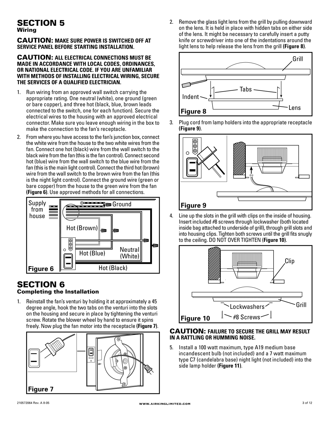
Installation is made easy with the Air King DRLC107, as it is designed to fit under cabinets, making it perfect for smaller spaces. This hood is suitable for both ducted and ductless installations, which provides flexibility depending on your kitchen setup.
In summary, the Air King DRLC107 range hood combines powerful performance, a quiet operation, and an attractive design. Its advanced features and user-friendly controls make it an ideal choice for home cooks seeking to enhance their kitchen experience while keeping the air clean and fresh. Whether you are an occasional chef or a culinary enthusiast, the DRLC107 elevates your kitchen with both style and functionality.

