
UG-ASW224-1103 specifications
The Airlink UG-ASW224-1103 is a robust and versatile unmanaged Ethernet switch designed for various networking applications. It is particularly well-suited for industrial environments where reliability and performance are paramount. This switch is a part of the Airlink product line, known for their advanced networking solutions tailored to meet the demands of industrial automation, security, and communication systems.One of the main features of the UG-ASW224-1103 is its 24-port configuration, which provides ample connectivity for multiple devices. The switch supports 10/100/1000 Mbps auto-sensing Ethernet ports, allowing for seamless integration with both legacy and modern network equipment. This feature facilitates high-speed data transfer and ensures that users can achieve optimal performance under varying network loads.
The build quality of the Airlink UG-ASW224-1103 is another significant characteristic. It is constructed with a durable metal housing, which helps to withstand the rigors of harsh environments, such as extreme temperatures, dust, and vibrations. This makes it an ideal solution for manufacturing plants, warehouses, and outdoor applications where environmental factors can impact performance.
In terms of technology, the UG-ASW224-1103 employs advanced switching capabilities, including MAC address learning and addressing for improved data flow control. The switch operates at Layer 2 of the OSI model, which means it directs traffic between devices on the same network effectively. This enhances overall network efficiency and reduces the likelihood of bottlenecks.
Power consumption is a critical consideration for many organizations, and the UG-ASW224-1103 is designed to operate efficiently. With low power consumption requirements, it helps reduce operational costs while maintaining high performance. Additionally, this switch is fanless, contributing to its silent operation, which is a significant advantage in noise-sensitive environments.
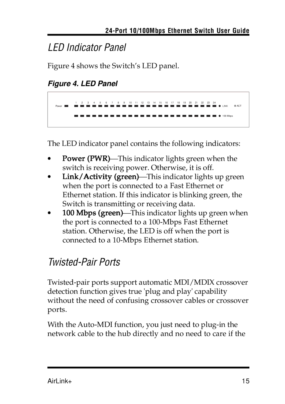
The Airlink UG-ASW224-1103 is also designed with easy installation in mind. Its compact size and plug-and-play functionality make it user-friendly, requiring minimal configuration. The LED indicators provide real-time status updates, allowing users to monitor network performance easily.
In summary, the Airlink UG-ASW224-1103 is a powerful unmanaged Ethernet switch that combines durability, efficiency, and advanced technologies tailored for industrial environments. Its extensive functionalities make it an excellent choice for businesses seeking reliable networking solutions to support their operations.