Connect the PC cable between the PC INPUT on the TV and the PC output on your PC. Note: You can use YPbPr to VGA cable (not supplied) to enable YPbPr signal via VGA input. WARNING: You cannot use VGA and YPbPr at the same time.
5.SPDIF Out outputs audio signals of the currently watched source.
Use an SPDIF cable to trasfer audio signals to a device that has SPDIF input.
V+ | V+ |
6. DC 12 V Input is used for connecting the supplied power adaptor. V- |
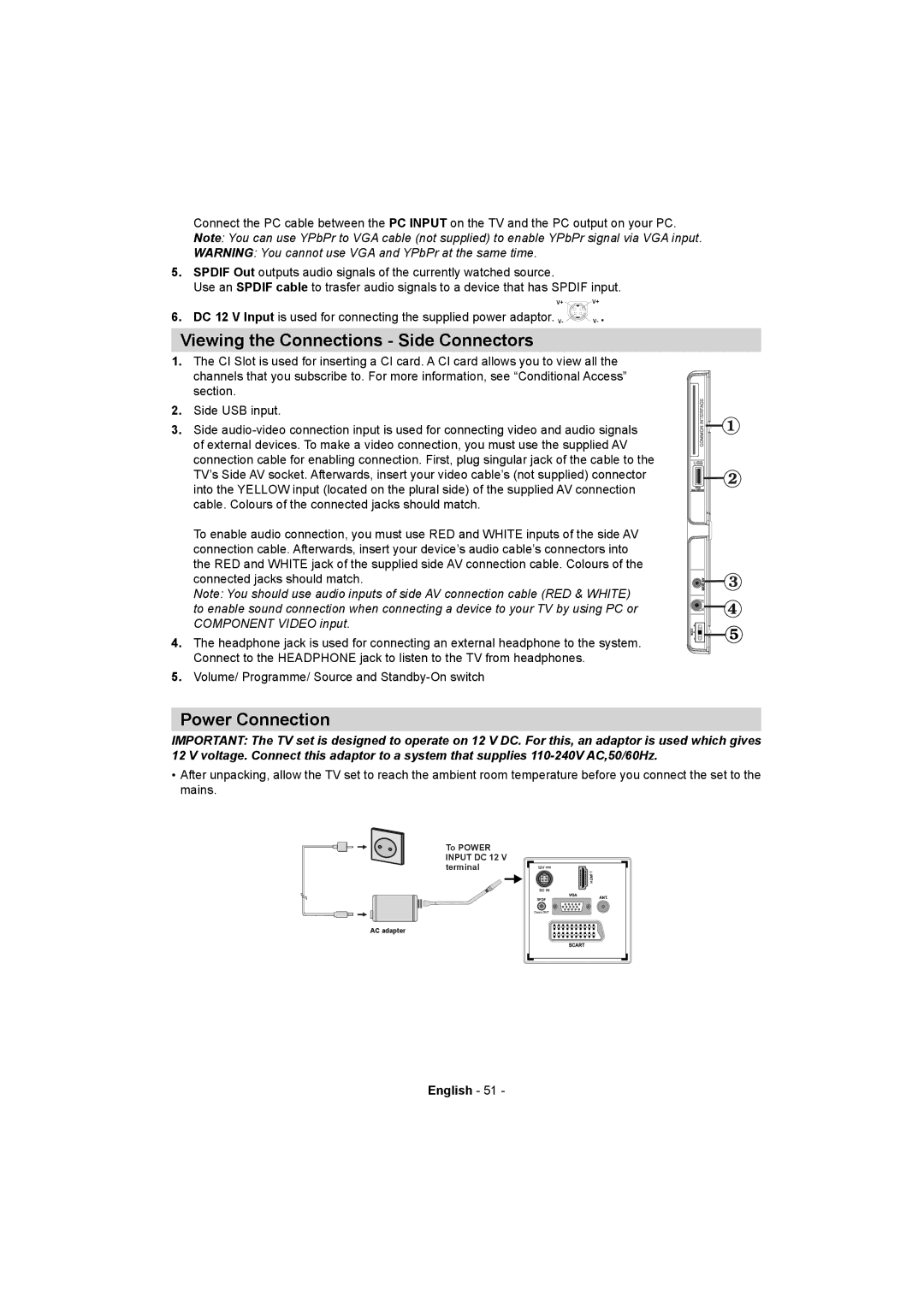
Viewing the Connections - Side Connectors
1.The CI Slot is used for inserting a CI card. A CI card allows you to view all the channels that you subscribe to. For more information, see “Conditional Access” section.
2.Side USB input.
3. Side
To enable audio connection, you must use RED and WHITE inputs of the side AV connection cable. Afterwards, insert your device’s audio cable’s connectors into the RED and WHITE jack of the supplied side AV connection cable. Colours of the connected jacks should match.
Note: You should use audio inputs of side AV connection cable (RED & WHITE) to enable sound connection when connecting a device to your TV by using PC or COMPONENT VIDEO input.
MODE o
4.The headphone jack is used for connecting an external headphone to the system. Connect to the HEADPHONE jack to listen to the TV from headphones.
5.Volume/ Programme/ Source and
Power Connection
IMPORTANT: The TV set is designed to operate on 12 V DC. For this, an adaptor is used which gives 12 V voltage. Connect this adaptor to a system that supplies
•After unpacking, allow the TV set to reach the ambient room temperature before you connect the set to the mains.
To POWER INPUT DC 12 V terminal
AC adapter
12V |
1MI DH |
DC IN |
SPDIF |
Coax.OUT |
English - 51 -