|
| Operation | |
4 Operation |
|
| |
Control concept | There are 16 rotary knobs on the front panel. These are labelled "IN 1" to "IN 12", "SYSTEM | ||
|
| CONTROL", "OUT 1", "OUT 2" and "HEADPHONE". | |
|
| The rotary knobs on the inputs are each surrounded by an LED ring with 15 yellow LEDs, one | |
|
| green LED and one red LED. The rotary knob "SYSTEM CONTROL" and the rotary knobs on | |
|
| the outputs are surrounded by 15 yellow LEDs. The control display under the outputs has 6 | |
|
| green, one yellow and one red LED. | |
|
| The LED rings help to visualise the rotary knob setting or display signal levels. | |
Configuring DMM 12BC |
|
| |
|
|
|
|
|
| Please read the instructions for connecting your microphones and auxiliary equipment under |
|
|
| Installation and Connection (Page 49). |
|
|
| NOTE |
|
|
| Configure the connected microphones and auxiliary equipment using the slide switches and | |
|
| the gain controls on the rear panel of the DMM 12BC: | |
|
| 1) If you use condenser microphones, check what supply voltage or what type of power | |
|
| supply they require. Switch on the phantom power if your condenser microphones are | |
|
| suitable for phantom power. To do so, set the "PHANT. PWR" slide switch to "ON". | |
|
|
| |
|
| Risk of damage |
|
|
| If you are using wireless microphones, it is essential to switch off the phantom power on those |
|
|
| inputs to which you have connected a receiver in order to avoid damaging the receiver. |
|
|
| ATTENTION |
|
|
| 2) For the gain of the input signals, choose between 0 dB and +57 dB. Use the respective | |
|
| gain control to do so. |
|
|
| A higher gain of the input signals is suitable for microphones with lower output levels. | |
|
| A lower gain is recommended for microphones with a high output level. | |
NOTE
3)Turn the unit on at the power switch.
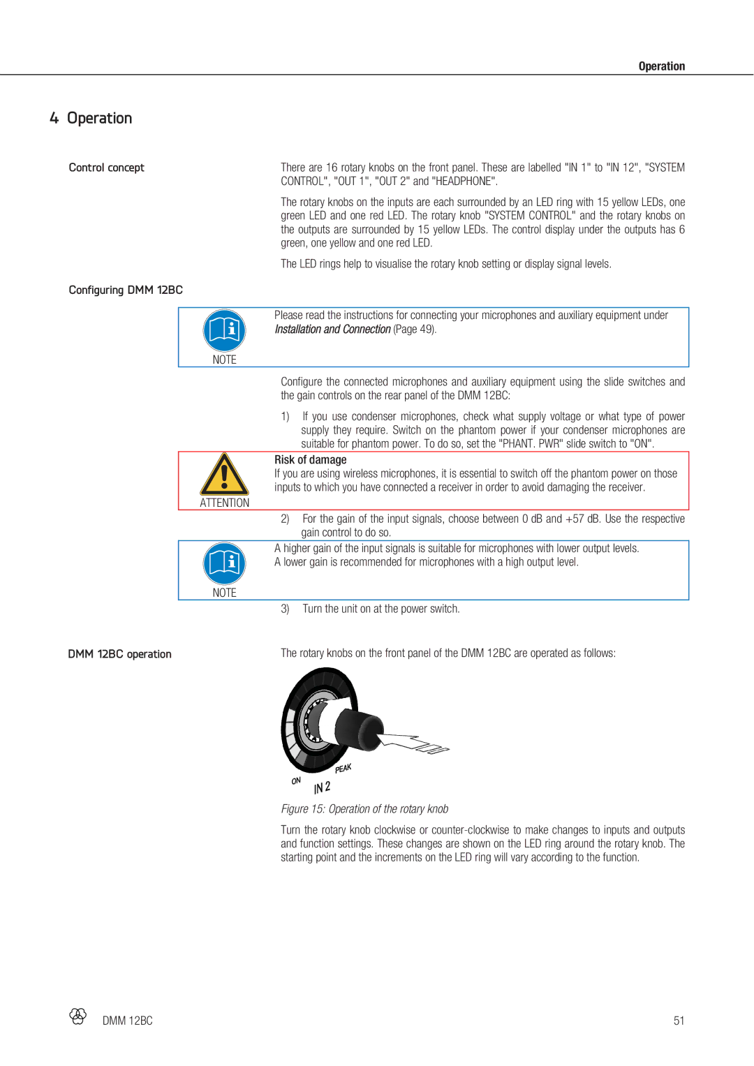
DMM 12BC operation | The rotary knobs on the front panel of the DMM 12BC are operated as follows: |
Figure 15: Operation of the rotary knob
Turn the rotary knob clockwise or
DMM 12BC | 51 |