Wireless
Page
Pioneer in Acoustics for Over 50 Years
Wireless Technology for the Future
Die DYN Series
How it all started …
120 DYN
Founders Dr. Rudolf Görike and Ing. Ernst Pless
180
12 a
Early products
Company name
Expansion course
Breakthrough
Peter Wolf
Rock me Amadeus
Turning point
AKG expands its activities in the wireless market
WMS
New research center
Case for wireless mics
HOW Radio Signals are Transmitted
Just like a radio set
Radio waves instead of cables
Positioning the receiver
Signal propagation
Wavelength
Rule no
Frequency Modulation FM
Bandwidth
Interference
Example of AKG WMS 40 carrier frequencies
Modular Solutions to Meet Individual Requirements
For presenters
Clip-on or head-worn microphone
Head-worn microphone for extreme
Activities like aerobics and sports
Handheld Mics for Lead and Backing Vocals
Volume
On/off switch
Microphone cleaning and maintenance
Angle of incidence
Rear panel and battery compartment
PT 40 Portable transmitter Mini XLR connector
HEAD-WORN Mics for Lead and Backing Vocals
Flexible antenna
Antennas
SR 40 diversity Receiver ON/OFF switch
AF LEDs
Alternative receivers Diversity LEDs
XLR connector
Battery compartment
SO 40 snapon transmitter Release button
Color code
Setting the squelch threshold
XLR connector pin 2 hot
TM 40 Transmitter module Status LED
Battery charging made easy
On/Off switch AF LEDs
Wireless and supremely flexible
3700M 3800M
880M
Cable compartment
MP 40 Micropen for Presenters
Microphone
Color code pen clip
PR 40 Portable receiver ON/OFF switch
MP 40 micropen in handheld mode
Detachable microphone
Put it in your pocket …
PT 40 Bodypack transmitter
More Goodies for Presenters
With C 444 L head-worn or C 417 L lavalier microphone
With proven D 880M microphone element
444 L
417 L
Avoiding feedback
Training communications
Wireless Systems for Maximum Mobility
PT 40 care
PR 40 Portable receiver
Radio Links for Portable Instruments
AKG WMS 40 UHF for Instruments
MicroMic C 411 L pickup
Connecting to microphone or line inputs
Instrument MicroMics
Instrument MicroMic Instrument MicroMics
Accessories
GB 40 Guitarbug for Guitar and Bass
Jack plug
Guitar system in a bag
FlexJack for all electric guitar models
FlexJack for all electric bass models
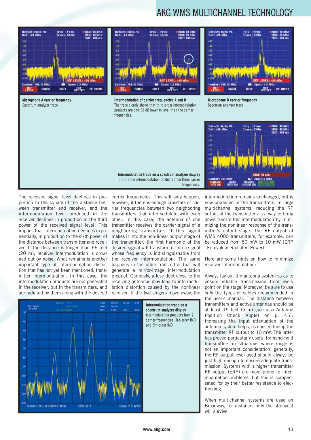
HOW Multichannel Technology Works
WMS frequency band with TV transmitter
Intermodulation
Use before each performance
Automatic frequency setup
Multipath transmission
Shadow loss
Troubleshooting Hints
Problem no sound microphone does not function
Problem poor audio
Modular Solutions for Custom Reqirements
Status LEDs
SR 400 Receiver On/Off switch Recessed level control
Backlit LC display
Metal case
Rehearsal mode
Auto setup
Range of accessories for complex applications
Infrared transmission
Extremely rugged spring steel mesh grill
On-Mute/Program-Off switch
Infrared sensor
HT 400 Handheld transmitter Display
Jack for external mute switch
Rugged mini XLR connector
Battery status display Frequency preset LCD display
Frequency in MHz Low battery capacity warning
User Friendly Quick Charger
Input jack for a local or central power supply e.g., PSU
Locking DC jack
Integrated charging contacts for direct charging
AB 4000 Antenna booster
PSU 4000 Central power supply unit
RA 4000 B Omnidirectional wideband booster antenna
HPA 4000 Headphone amplifier
IP 3 Intercept
Setting UP Multichannel Systems
Microphone a carrier frequency
Spectrum analyzer trace
Frequencies
Frequency Management a good idea for any multichannel system
Far-near difference
Here is a proven way to add clean frequencies
Stage a Stage B
Band I + 0,15
Modular Solutions for Professional Requirements
Signal loss caused by the audience
SELECTING, Placing and Using Antennas
Skin Fat
Muscle Cartilage
Cable position a Cable position B
SELECTING, PLACING, and Using Antennas
Cable type Impedance
Gage
Stadium example
Stadium theater, opera house example
Short antenna cable runs Drawbacks
Speech Vocals Guitar/Bass Instruments
Live sound
TV studio Theater
CU 4000/BP HUB 4000 Network concentrator
SRA 1 Passive wideband dirctional antenna
RA 4000 B
Frequency presets
Battery status readout
Automatic gain setting
Battery compartment Jog switch
Silent Mode setting
Jack for remote Mute switch
Inscribable color code element Magnesium body
Hidden pilot tone
Backlit display Half-rack 19 all-metal case
CUTTING-EDGE True Diversity Receiver
Programmable status display
SR 4000 Receiver
Environment Scan and Rehearsal Mode
Battery life display
Environment Scan
Professional XLR and jack outputs
Charging status display LED Recovery key and LED
Intelligent WAY to Power WMS 4000 Transmitters
CU 4000 Charging unit Lockable DC jack
Such as a PSU
CU 4000 Charging unit in a flight case
Integrated temperature sensor
Internal RAM
Data interface to transmitter electronics
BNC antenna outputs
BNC antenna inputs
Daisy-chaining outputs
AKG WMS PS
Antennas Tailored to Every Situation
Cabling example/cable lengths
Selecting and placing antennas
SRA 1 Passive wideband directional antenna
ASU 4000 Remote powerd adapter for antennas
SRA 2B Active wideband directional antenna
ZAPD-21 Antenna combiner
Link Between the WMS 4000 and a PC Network
Standard PC accessories. This allows you to
As RF levels on site. This makes it incredibly
Example WMS 4000/PC network
Get a Cup Setup Mode Moving PC Rehearsal Mode
You can even set up the basic parameters
Your Computer AS a WMS 4000 Control Center
Ensures maximum operating reliability
AKG WMS 4000 Power Supply
Monitoring Without a Mixer
Recommended headphones
Line input jacks, DC input lockable Jog control
Studio
Seminars
Specification Amount Description
PSU
RA 4000 B
Example 10-CHANNEL System for Tour Sound
Tour Sound
Amount Description
AKG WMS Practical Examples
Vienna Konzerthaus
Example 16-CHANNEL System for Mobile USE
WMS 4000 mobile rack
WMS 4000 Wiring
Gala Musical Couples, August
Detailed system layout is shown on the following pages
WMS 4000 16-CHANNEL Setup
AKG WMS Practical Examples
High-tech for pure enjoyment
Example 46-CHANNEL System for AN Opera House
Stage
Channels
Channels
Specification
WMS 4000 1-CHANNEL Setup
AKG WMS Practical Examples
Violin and viola
Guitar
Banjo
See guitar. top right
Clarinet
Saxophone
Tubas
Trombone
Bars and clubs
AV/sound company
Sound systems
Meeting and social rooms
Microtools HT/PT
AKG Wireless Systems AT a Glance
ALL the Specs AT a Glance
System
MP 40 micropen
Mounting kit, 2 antennas
PR 40 diversity
Definitions from a to Z
Distortion Environment
Electromagnetic Wave Spectrum
Directional Antenna
Diversity
Feedback
Phantom Power
Frequency Management
Frequency Modulation
Cardioid
Hypercardioid Ultra-directional
Pop Noise
Pressure Gradient Microphone
Signal-to-noise S/N Ratio
Signal Loss
Reflection
Remote Antenna
Selected Keywords
Index
Appendix
Appendix
Appendix
Appendix
Appendix
Page
AKG ACOUSTICS, U.S