MAINTENANCE
CUTTERBAR ADJUSTMENTS
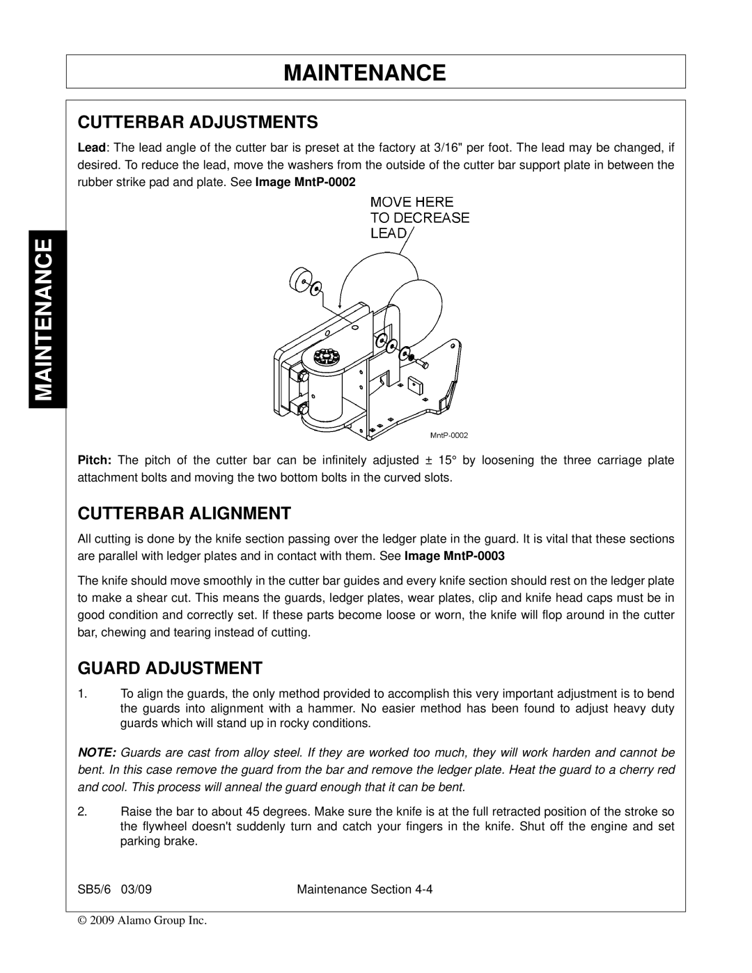
Lead: The lead angle of the cutter bar is preset at the factory at 3/16" per foot. The lead may be changed, if desired. To reduce the lead, move the washers from the outside of the cutter bar support plate in between the rubber strike pad and plate. See Image
MAINTENANCE
Pitch: The pitch of the cutter bar can be infinitely adjusted ± 15° by loosening the three carriage plate attachment bolts and moving the two bottom bolts in the curved slots.
CUTTERBAR ALIGNMENT
All cutting is done by the knife section passing over the ledger plate in the guard. It is vital that these sections are parallel with ledger plates and in contact with them. See Image
The knife should move smoothly in the cutter bar guides and every knife section should rest on the ledger plate to make a shear cut. This means the guards, ledger plates, wear plates, clip and knife head caps must be in good condition and correctly set. If these parts become loose or worn, the knife will flop around in the cutter bar, chewing and tearing instead of cutting.
GUARD ADJUSTMENT
1.To align the guards, the only method provided to accomplish this very important adjustment is to bend the guards into alignment with a hammer. No easier method has been found to adjust heavy duty guards which will stand up in rocky conditions.
NOTE: Guards are cast from alloy steel. If they are worked too much, they will work harden and cannot be bent. In this case remove the guard from the bar and remove the ledger plate. Heat the guard to a cherry red and cool. This process will anneal the guard enough that it can be bent.
2.Raise the bar to about 45 degrees. Make sure the knife is at the full retracted position of the stroke so the flywheel doesn't suddenly turn and catch your fingers in the knife. Shut off the engine and set parking brake.
SB5/6 03/09 | Maintenance Section |
© 2009 Alamo Group Inc.