Installation and Connection Instructions | 4 | ||||||
|
|
|
|
|
|
|
|
|
|
|
|
|
|
|
|
|
|
|
|
| CAUTION |
|
|
|
|
|
|
|
|
|
|
|
|
|
|
| Ensure that the machine is installed on a level floor of |
|
|
|
|
|
|
| sufficient strength and that the recommended clearances |
|
|
|
|
|
|
| for inspection and maintenance are provided. Never |
|
|
|
|
|
|
| allow the inspection and maintenance space to be |
|
|
|
|
|
|
| blocked. |
|
|
|
|
|
| Surface |
| ||
|
|
|
| The machine must be securely fixed on a flat surface (metal base, |
| ||
|
|
|
| concrete or solid ground). The anchoring is to be done on the |
| ||
|
|
|
| 4 provided places (A) (See Label 1) in the holes on the corner of the | |||
|
|
|
| base. (See Mounting Bolt Hole Locations) |
| ||
|
|
|
| The machine must be placed entirely level. For easy maintenance it |
| ||
|
| A | A | is recommended to keep a minimal distance of 600 mm - 23.62 inch |
| ||
Label 1
between the wall and the back of the machine.
If several machines are placed next to each another, there should be a minimal distance of 30 mm - 1.18 inch between each machine.
|
| D |
E |
| C |
F |
|
|
| D |
|
B | C | G |
| ||
|
| |
A |
|
|
Label 2
D |
E |
C |
B |
A |
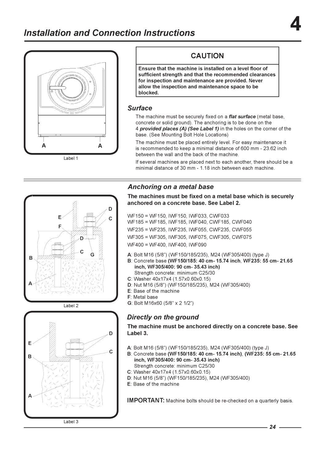
Anchoring on a metal base
The machines must be fixed on a metal base which is securely anchored on a concrete base. See Label 2.
WF150 = WF150, IWF150, IWF033, CWF033
WF185 = WF185, IWF185, IWF040, CWF185, CWF040
WF235 = WF235, IWF235, IWF055, CWF235, CWF055
WF305 = WF305, IWF305, IWF075, CWF305, CWF075
WF400 = WF400, IWF400, IWF090
A: Bolt M16 (5/8”) (WF150/185/235), M24 (WF305/400) (type J)
B: Concrete base (WF150/185: 40 cm- 15.74 inch, WF235: 55 cm- 21.65 inch, WF305/400: 90 cm- 35.43 inch)
Strength concrete: minimum C25/30
C: Washer 40x17x4 (1.57x0.60x0.15)
D: Nut M16 (5/8”) (WF150/185/235), M24 (WF305/400)
E: Base of the machine
F: Metal base
G: Bolt M16x60 (5/8” x 2 1/2”)
Directly on the ground
The machine must be anchored directly on a concrete base. See Label 3.
A: Bolt M16 (5/8”) (WF150/185/235), M24 (WF305/400) (type J)
B: Concrete base (WF150/185: 40 cm- 15.74 inch), (WF235: 55 cm- 21.65 inch, WF305/400: 90 cm- 35.43 inch)
Strength concrete: minimum C25/30
C: Washer 40x17x4 (1.57x0.60x0.15)
D: Nut M16 (5/8”) (WF150/185/235), M24 (WF305/400)
E: Base of the machine
IMPORTANT: Machine bolts should be
Label 3
24