AT-8800 Series Switch
Page
Contents
AT-8800 Series Switch User Guide
Operating the switch
Maintenance and Troubleshooting
Page
Why Read this User Guide?
Introducing the AT-8800 Series Switch
Chapter
AT-8800 Series Switch Documentation Set
Where To Find More Information
Online Technical Support
Features of the AT-8800 Series Switch
Introduction
Software Features
Management Features
Special Feature Licences
Do if You Clear Flash Memory Completely on
This Chapter
Getting Started with the Command Line Interface CLI
Terminal Communication Parameters
Connecting a Terminal or PC
Parameters for terminal communication Value
Assigning an IP Address
Enter the password at the password prompt
Getting Started with the Command Line Interface CLI
Logging
To change the IP address for an interface, enter the command
Setting Routes
Choosing a Password
Changing a Password
To add a static route, enter the command
Not available
Using the Commands
To display the current help file, enter the command
Getting Command Line Help
Aliases
Setting System Parameters
Enabling Special Feature Licences
Getting Started with the Graphical User Interface GUI
Getting Started with the Graphical User Interface GUI
Supported browsers and operating systems
What is the GUI?
Accessing the Switch via the GUI
Browser and PC Setup
Http Proxy Servers
See Option 2 Installing the Switch into the LAN on
Establishing a Connection to the Switch
See Option 3 Connecting to an Installed Switch on
See Option 1 Configuring the Switch before Installation on
Use this procedure if
Option 1 Configuring the Switch before Installation
See Http Proxy Servers on page 23 for more information
Plug the switch into the LAN
Option 2 Installing the Switch into the LAN
Default username is manager
At the login prompt, enter the user name and password
Assign the vlan1 interface an IP address
See Secure Access on page 29 for more information
If necessary, bypass the Http proxy server
Option 3 Connecting to an Installed Switch
Find out the IP address of the switch’s interface
Select a PC
Create a Security Officer user account
Secure Access
To enable system security, use the command
Then enter the password for CIPHER, sbr4y3
To create an RSA key pair, use the command
System Status
System Status
Quality of Service and traffic filters
Using the GUI Navigation and Features
Configuration Menu
Using Configuration Pages
An example of a configuration page with a selection table
Editable Fields
Monitoring Menu
Management Menu
Changing the Password
Diagnostics Menu
Context Sensitive GUI Help
Combining GUI and CLI Configuration
Saving Configuration Entered with the GUI
Configuring Multiple Devices
Upgrading the GUI
To upgrade the GUI
Then delete the GUI resource file, using the command
Load the new file onto the switch
Install the new file as the preferred GUI
Troubleshooting
Point your web browser at the switch’s IP address
Deleting Temporary Files
Accessing the Switch via the GUI
Traffic Flow
Time and NTP
Solution
Solutions
IP Addresses and Dhcp
Loading Software
Page
A Security Officer prompt looks like
Using Scripts on
User Accounts and Privileges
Snmp and MIBs on
Login
To display the current operating mode, enter the command
Normal Mode and Security Mode
Operating the switch
Specific Parameters
Storing Files in Flash Memory
Remote Management
Example output from the Show File command
Using Scripts
Storing Multiple Scripts
Saving the Switch’s Configuration
File Naming Conventions
Loading and Uploading Files
File extensions and file types Extension File type/function
SPA
Loading Files
Download the patch file
Setting Loader Defaults
Example Load a Patch File Using Http
To load a patch file Configure the Loader
To upload a log file
Uploading Files From the Switch
Example Upload a Configuration File Using Tftp
More information
Upgrading Switch Software
To upgrade to a new software release
Example Upgrade to a New Software Release Using
Load the new release file onto the switch
Test the release
Enter the licence password for the software release
Make the release the default permanent release
Enter licence information for the release
To upgrade to a new patch file
Example Upgrade to a new patch file
Check that the file is successfully loaded
Snmp and MIBs
Using the Built-in Editor
For More About Operations and Facilities
Where interface is the name of an interface, such as vlan11
AT-8800 Series Switch User Guide
Enabling and Disabling Switch Ports
Switch Ports
To display information about switch ports, use the command
To enable or disable a switch port, use the commands
STP
Autonegotiation of Port Speed and Duplex Mode
Speed 10/100
Port Trunking
Show VLAN=ALL
Packet Storm Protection
Layer 2 Switching
Port Mirroring
Port security
Virtual Local Area Networks VLANs
Example output from the Show Switch Port Intrusion command
Tpid
Vlan Tagging
Format of user priority and Vlan data in an Ethernet frame
Vlan Membership using Vlan Tags
Vlan Membership of Untagged Packets
Vlan membership of example of a network using tagged ports
Member ports
Vlans with untagged ports
Creating VLANs
To destroy a VLAN, use the command
To add tagged ports to a VLAN, use the command
Protected VLANs
Summary of Vlan tagging rules
Vlan Interaction with STPs and Trunk Groups
Generic Vlan Registration Protocol Gvrp
Layer 2 Switching Process
Ingress Rules
Learning Process
Forwarding Process
Layer 2 Filtering
Example output from the Show Switch Filter command
Egress Rules
Quality of Service
Spanning Tree Modes
Spanning Tree Protocol STP
Spanning tree port states State Meaning
Spanning Tree and Rapid Spanning Tree Port States
Rapid Spanning Tree port states State Meaning
Configuring STP
SET STP=stpnameALL PRIORITY=0..65535
Example output from the Show STP command
Do not occur
Parameter Meaning
Switch Max Age
To display STP port information, use the command
Example output from the Show STP Port command
94AT-8800 Series Switch User Guide
To show STP counters, use the command
Discarded
96AT-8800 Series Switch User Guide
Receive
Transmit
Igmp Snooping
Interfaces to Layer 3 Protocols
Disable Igmpsnooping
Group List
Example output from the Show IP Igmp command
Parameters
Triggers
Event
Description
Layer
IP Multicasting
Then use either of the following commands
Displays the interfaces enabled for IP routing Figure
Internet Protocol IP
Novell IPX
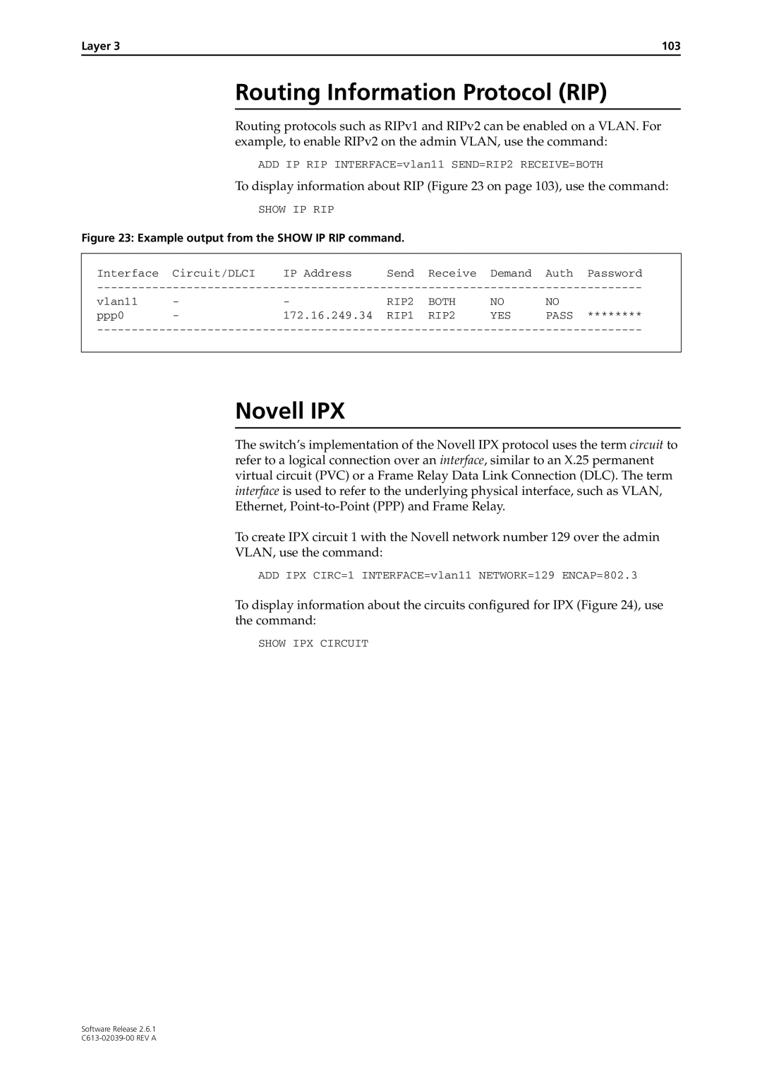
Routing Information Protocol RIP
Layer 103
AppleTalk
Example output from the Show IPX Circuit command
Layer 105
Resource Reservation Protocol Rsvp
Page
Maintenance and Troubleshooting
Switch startup messages
How the Switch Starts Up
Set system territory
How to Avoid Problems
Watch for software updates
If you accidentally do this, you will need to
What to Do if You Clear Flash Memory Completely
What to Do if the PPP Link Disconnects Regularly
What to Do if Passwords are Lost
Getting the Most Out of Technical Support
Maintenance and Troubleshooting 113
Resetting Switch Defaults
Checking Connections Using Ping
To get debugging output, enter the command
Telnet Fails
Troubleshooting IP Configurations
To set Ping defaults, enter the command
Stop a Ping that is in progress, enter the command
Maintenance and Troubleshooting 115
Troubleshooting Dhcp IP Addresses
Your switch is acting as a Dhcp client
Your switch is acting as a Dhcp server
No Routes are Visible to the Remote Router
Troubleshooting IPX Configurations
To check that the PPP link is active, enter the command
Local Workstations Can Not Access Remote Servers
Check route tables
Using Trace Route for IP Traffic
To halt a trace route that is in progress, enter the command