Installation & Safety Guide | 9 |
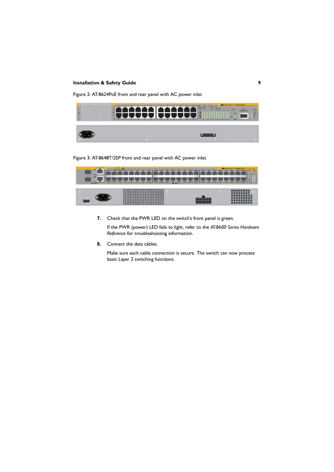
Figure 2: AT-8624PoE front and rear panel with AC power inlet
| 1 | 3 | 5 | 7 | 9 | 11 |
25 | 26 |
|
|
|
|
|
| 2 | 4 | 6 | 8 | 10 | 12 |
13 | 15 | 17 | 19 | 21 | 23 |
| 100 LINK |
| ACT | 10 LINK |
| ACT |
|
|
|
|
| ||
|
|
|
|
|
|
| FULL DUP |
|
| HALF DUP | COL |
|
|
|
|
|
|
| |
|
|
|
|
|
|
| PD ON |
|
| PD ERR |
| MAX CURRENT |
|
|
| MODE | STATUS | ||
|
|
|
|
|
|
|
|
|
|
|
|
|
|
|
|
| |||
|
|
|
|
|
| 1 | 3 | 5 | 7 | 9 | 11 | 13 | 15 | 17 | 19 | 21 | 23 | TERMINAL PORT |
|
|
|
|
|
|
|
|
|
|
|
|
|
|
|
|
|
|
|
| FAULT |
|
|
|
|
|
|
|
|
|
|
|
|
|
|
|
|
|
|
| MASTER |
|
|
|
|
|
|
|
|
|
|
|
|
|
|
|
|
|
|
| RPS |
|
|
|
|
|
|
|
|
|
|
|
|
|
|
|
|
|
|
| PWR |
14 | 16 | 18 | 20 | 22 | 24 | 2 | 4 | 6 | 8 | 10 | 12 | 14 | 16 | 18 | 20 | 22 | 24 |
|
|
Figure 3: AT-8648T/2SP front and rear panel with AC power inlet
|
|
|
|
| LINK | 49R | MODE |
|
| 49 |
| LINK |
|
|
|
|
|
|
|
|
|
|
|
|
| SFP |
| LINK |
|
|
|
|
|
|
|
|
|
|
|
|
| 50 |
|
| LINK | 50R | MODE |
| |
STATUS |
|
COL | FLT |
SPD | MSTR |
FDX | RPS |
ACT | PWR |
MODE |
|
7.Check that the PWR LED on the switch’s front panel is green.
If the PWR (power) LED fails to light, refer to the
8.Connect the data cables.
Make sure each cable connection is secure. The switch can now process basic Layer 2 switching functions.