8 |
|
.
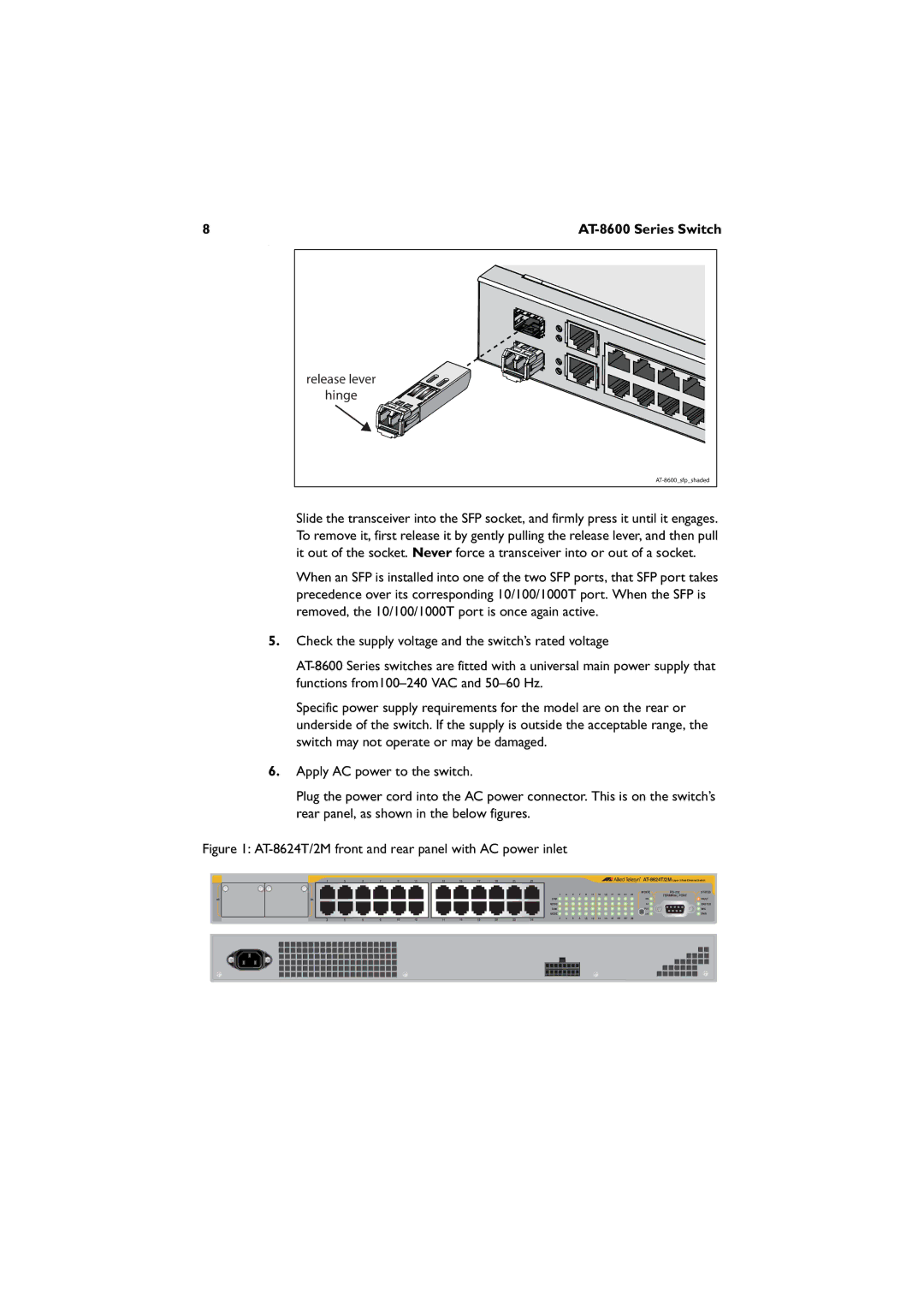
release lever |
hinge |
Slide the transceiver into the SFP socket, and firmly press it until it engages. To remove it, first release it by gently pulling the release lever, and then pull it out of the socket. Never force a transceiver into or out of a socket.
When an SFP is installed into one of the two SFP ports, that SFP port takes precedence over its corresponding 10/100/1000T port. When the SFP is removed, the 10/100/1000T port is once again active.
5.Check the supply voltage and the switch’s rated voltage
Specific power supply requirements for the model are on the rear or underside of the switch. If the supply is outside the acceptable range, the switch may not operate or may be damaged.
6.Apply AC power to the switch.
Plug the power cord into the AC power connector. This is on the switch’s rear panel, as shown in the below figures.
Figure 1: AT-8624T/2M front and rear panel with AC power inlet
| 1 | 3 | 5 | 7 | 9 | 11 |
25 | 26 |
|
|
|
|
|
| 2 | 4 | 6 | 8 | 10 | 12 |
13 | 15 | 17 | 19 | 21 | 23 |
|
|
|
|
|
|
|
|
|
|
| |||
|
|
|
|
|
|
|
|
|
|
|
|
|
|
|
|
| MODE | STATUS | |
|
|
|
|
|
| 1 | 3 | 5 | 7 | 9 | 11 | 13 | 15 | 17 | 19 | 21 | 23 | TERMINAL PORT |
|
|
|
|
|
|
| LINK |
|
|
|
|
|
|
|
|
|
| COL |
| FAULT |
|
|
|
|
|
| MODE |
|
|
|
|
|
|
|
|
|
| 100 |
| MASTER |
|
|
|
|
|
| LINK |
|
|
|
|
|
|
|
|
|
| FULL |
| RPS |
|
|
|
|
|
| MODE |
|
|
|
|
|
|
|
|
|
| ACT |
| PWR |
14 | 16 | 18 | 20 | 22 | 24 | 2 | 4 | 6 | 8 | 10 | 12 | 14 | 16 | 18 | 20 | 22 | 24 |
|
|