Altinex manual Installing Your AP445-401, Front Panel Operation, Selecting the Input

Models: AP445-401

1 17
Download 17 pages 22.88 Kb
Page 8
Image 8

SPECIAL APPLICATION

INSTALLING YOUR AP445-401

6

Step 1. Determine a good location for placing the AP445-401.For best results, choose a location that minimizes cable lengths.

Step 2. Connect a cable from each video source to its corresponding video input connector on the AP445-401. The Component and Composite video input connectors are BNC type. If using RCA cables, use the RCA to BNC adapters provided with the unit.

Step 3. Connect a cable from each audio source to its corresponding input. Take care to ensure the video and audio inputs match.

Step 4. Connect the video output connector of the AP445-401to the display device with a VGA type cable for RGBHV displays or a YPbPr cable for Component Video.

Step 5. Determine which audio output is to be used. Either the adjustable balanced stereo using the terminal block or the fixed unbalanced stereo using the 3.5mm jack.

Step 6. Connect the audio output connector of the AP445-401to the speakers or amplifier using the appropriate audio cable.

Step 7. Connect the AP445-401to AC power. Then unit is now operational.

Step 8. The default input selection is the S-Video port. In order to change the input to other than Composite Video, use the front panel buttons or RS-232 control.

NOTE: RS-232 operation: Use AVSnap or other RS-232 communication software. Follow the instructions defined in section 7.3 for the IN command.

Step 9. Select the correct output resolution mode for the display device.

Step 10. Adjust the display properties for optimal image quality.

OPERATION

7

7.1 FRONT PANEL OPERATION

Front panel control is available using push buttons with LED indicators. The front panel may be used to select the input, adjust image properties, adjust the volume and select the output resolution.

The front panel buttons may be locked using RS-232 control. If pressing the buttons on the front panel has no effect, use RS-232 control to verify the front panel is not locked.

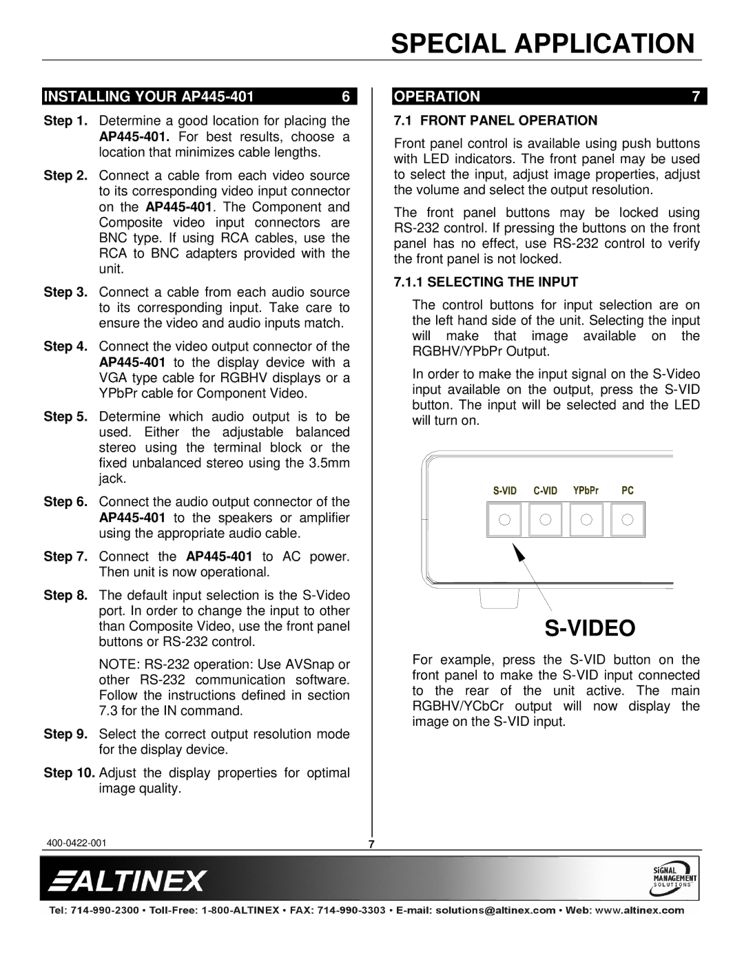
7.1.1 SELECTING THE INPUT

The control buttons for input selection are on the left hand side of the unit. Selecting the input will make that image available on the RGBHV/YPbPr Output.

In order to make the input signal on the S-Video input available on the output, press the S-VID button. The input will be selected and the LED will turn on.

S-VIDEO

For example, press the S-VID button on the front panel to make the S-VID input connected to the rear of the unit active. The main RGBHV/YCbCr output will now display the image on the S-VID input.

400-0422-001

7

Page 8
Image 8
Altinex manual Installing Your AP445-401, Front Panel Operation, Selecting the Input