CP7317RS specifications
The Altinex CP7317RS is a cutting-edge solution designed for advanced audio-visual applications. This versatile controller is a part of Altinex's broad portfolio of professional audio-visual solutions, known for enhancing the user experience in environments like conference rooms, classrooms, and auditoriums. The CP7317RS controller stands out with its impressive array of innovative features, technologies, and characteristics.One of the most notable features of the CP7317RS is its compact design, which allows for easy integration into various settings without taking up too much space. Despite its small footprint, the controller is packed with functionality, enabling users to manage multiple AV devices seamlessly. Its user-friendly interface simplifies operation, allowing both novices and seasoned professionals to navigate its capabilities with ease.
The CP7317RS supports a variety of input and output formats, ensuring compatibility with a wide range of audiovisual equipment. Users can connect multiple sources such as computers, projectors, and other multimedia devices, making it a versatile solution for multimedia presentations. The controller's ability to handle HDMI, VGA, and other input types makes it ideal for diverse applications, supporting both legacy and modern technologies.
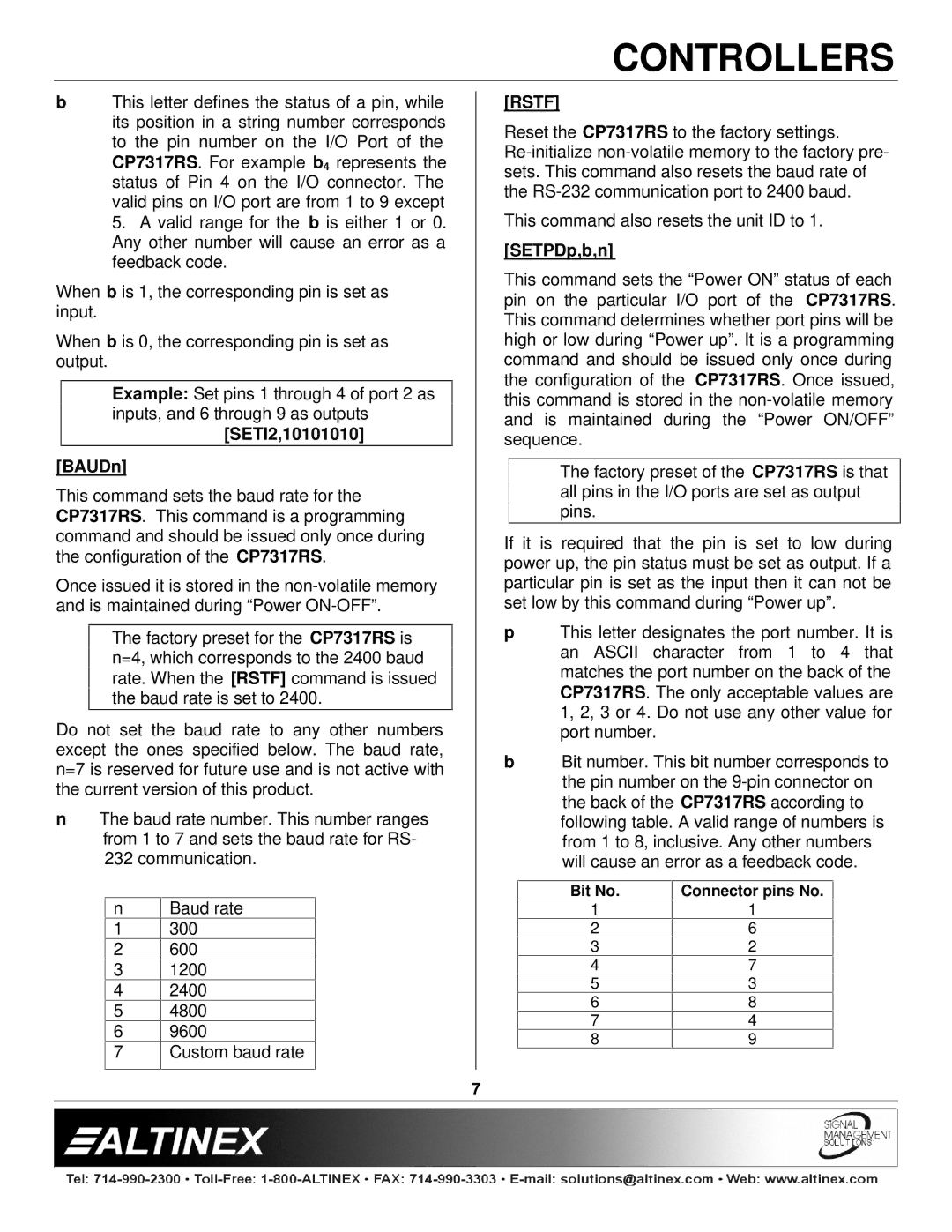
Another key feature of the Altinex CP7317RS is its extensive control options. The device supports both RS-232 and TCP/IP communications, allowing for remote control and monitoring of AV systems. This remote access capability is particularly advantageous in large venues where equipment is located in different areas. Users can control various functions, such as switching inputs, adjusting volume levels, and managing video outputs, all from a central location.
Moreover, the CP7317RS is equipped with advanced programmable functionality. Users can customize settings according to specific needs, creating tailored control interfaces that streamline operations. This programmability enhances efficiency, ensuring that AV systems operate smoothly during presentations and events.
In addition to its operational features, the CP7317RS is built with reliability in mind. Altinex is known for its quality construction, and this controller is no exception. It has been designed to perform consistently in the demanding environments typical of professional AV setups.
Overall, the Altinex CP7317RS is an invaluable asset for any audio-visual setup. With its blend of compact form, extensive connectivity options, remote control capabilities, and customizable features, it stands as a premier choice for those seeking to enhance their AV experience. Whether in corporate, educational, or entertainment venues, the CP7317RS promises to deliver exceptional performance and user satisfaction.

