INTERFACES
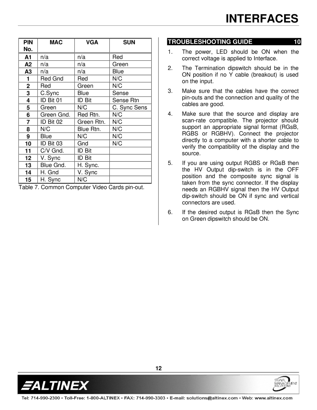
PIN | MAC | VGA | SUN |
No. |
|
|
|
|
|
|
|
TROUBLESHOOTING GUIDE | 10 |
1. The power, LED should be ON when the |
A1
A2
A3
1
2
3
4
5
6
7
8
9
10
11
12
13
14
15
n/a
n/a
n/a
Red Gnd
Red
C.Sync
ID Bit 01
Green
Green Gnd.
ID Bit 02
N/C
Blue
ID Bit 03
C/V Gnd.
V.Sync Blue Gnd. H. Gnd H. Sync
n/a
n/a
n/a
Red
Green
Blue
ID Bit
N/C
Red Rtn.
Green Rtn.
Blue Rtn.
N/C
Gnd
ID Bit
ID Bit
H.Sync.
V. Sync N/C
Red
Green
Blue
N/C
N/C
Sense
Sense Rtn
C. Sync Sens
N/C
N/C
N/C
N/C
N/C
| correct voltage is applied to Interface. |
2. | The Termination dipswitch should be in the |
| ON position if no Y cable (breakout) is used |
| on the input. |
3. | Make sure that the cables have the correct |
| |
| cables are good. |
4. | Make sure that the source and display are |
| |
| support an appropriate signal format (RGsB, |
| RGBS or RGBHV). Connect the projector |
| directly to a computer with a shorter cable to |
| verify the compatibility of the display and the |
| source. |
5. | If you are using output RGBS or RGsB then |
| the HV Output |
| position and the composite sync signal is |
| taken from the sync connector. If the display |
Table 7. Common Computer Video Cards
needs an RGBHV signal then the HV Output |
connectors are used. |
6. If the desired output is RGsB then the Sync |
on Green dipswitch should be ON. |
12