Installation
2-15
Verifying Correct OperationThe following sections describe how to ensure that the units are correctly installed
and functioning properly.
Verifying Correct Operation of the Indoor Unit
To verify proper operation, check the LED indicators located on the top panel of the
indoor unit as shown in Figure 2-6 on page 2-13, and as described in Table 2-2.
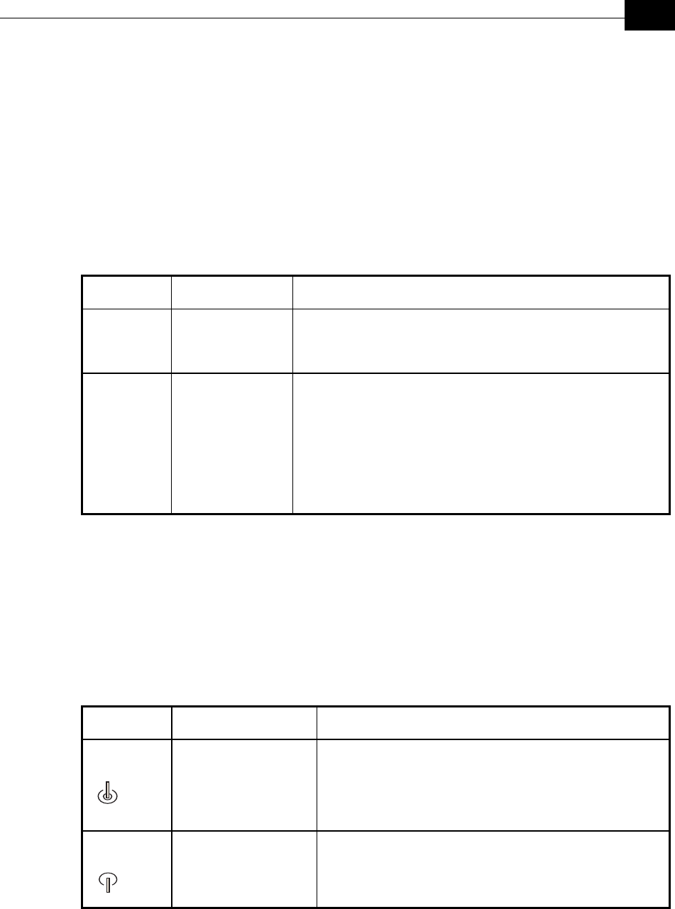
Name Description Functionality
POWER Power indication Orange - 48VDC is present on the Radio RJ45 port.
Off - No power is supplied to the Radio RJ45 port.
LINK Self Test and
Ethernet Link
indication
The LINK LED indicates end-to-end connection between the
outdoor unit and the Ethernet connection to the indoor unit.
Off – No Ethernet connectivity has been detected between the
outdoor unit and the device connected to the indoor unit.
Green– Self-test passed and Ethernet connection is confirmed by the
outdoor unit (Ethernet integrity check passed).
Table 2-2: Indoor Unit LEDs
Verifying Correct Operation of the Outdoor
Unit
To verify proper operation, check the LED indicators located on the bottom panel of
the outdoor unit.
Name Description Functionality
WLAN
Wireless Link
Indicator
The green LED is updated every second. It will be turned on if
at least one data packet (excluding beacons) was transmitted
during the last second. Thus, it will stay on continuously when
there is high traffic. In lower traffic rates it will blink-where the
blinking rate is slower when there is less wireless traffic.
DC Power
Self Test and Power
indication
Green – Power is available and self-test passed.