150/RG specifications
The American DJ 150/RG is a powerful and versatile lighting fixture that has become a staple for DJs, event planners, and venues seeking to elevate their lighting setup. This dynamic light offers an array of features and technologies designed to enhance performances and create unforgettable atmospheres.One of the standout features of the American DJ 150/RG is its RGB color mixing capability. Utilizing a combination of red, green, and blue LEDs, the fixture can produce a wide spectrum of colors, allowing users to create vibrant and engaging lighting displays. This feature is particularly beneficial for creating mood lighting or for synchronizing colors with music during performances.
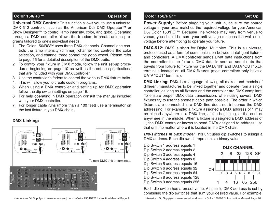
The 150/RG is equipped with advanced control options. It supports DMX512 protocol, allowing for precise control over multiple fixtures in a setup. This flexibility enables lighting designers to craft elaborate light shows that can match the rhythm and energy of the music being played. Users also have the option to operate the light in stand-alone mode, making it an excellent choice for smaller events where a full lighting rig may not be necessary.
In terms of construction, the American DJ 150/RG is designed with durability in mind. The fixture boasts a robust housing that can withstand the rigors of transportation and frequent use. Its compact size makes it easy to transport and set up, while still delivering professional-grade performance.
Another key characteristic of the 150/RG is its energy efficiency. With the use of LED technology, this fixture consumes significantly less power compared to traditional lighting sources. This feature not only saves on energy costs but also reduces the need for complex ventilation systems, as LEDs produce less heat.
The American DJ 150/RG also includes user-friendly controls. The fixture is equipped with an intuitive interface that allows for easy adjustments of colors, patterns, and effects. This user-centric design ensures that both novice and experienced users can quickly familiarize themselves with the light and make adjustments during their performances.
In summary, the American DJ 150/RG is an exceptional lighting fixture that combines versatility, durability, and energy efficiency. With its rich color mixing capabilities, advanced control options, and robust construction, it caters to the needs of DJs, event planners, and venues looking to create captivating and visually stunning experiences. Whether for a club, wedding, or live performance, the 150/RG stands out as a reliable choice for quality lighting solutions.

