VERTI PRO II™ | Operation |
|
|
Operating Modes: You can operate the VERTI PRO II™ in three different modes:
•
•Master/Slave mode - Allows you to daisy chain up to 4 fixtures together for a synchronized light show. The fixtures will react to sound chasing through several built in programs. You can also use the optional VertiPro/C remote control to change programs and blackout the units.
•DMX control mode - This function will allow you to control each fixtures DMX traits with a standard DMX 512 controller such as the American DJ® Show Designer™ or DMX Operator.™
NOTE:
Stand Alone Mode:
1.To operate a single unit or several units as individuals in stand alone mode, turn dip switch number 10 to the on position (see page 13) and plug the unit(s) in. If you are running more than one unit in stand alone mode do not link the units together.
2.Adjust the sensitivity knob on the bottom of the unit so the unit will react to sound and cycle through the internal chases. Turning the sensitivity knob in a clockwise direction will make the fixture more sensitive to sound, turning the sensitivity knob in counter- clockwise direction will make the fixture less sensitive to sound.
1.Using standard XLR microphone cables, daisy chain your units together via the XLR connectors on the rear of the unit. Remem- ber the Male XLR connector is the input and the Female XLR is the output. The first unit in (master) will use the female XLR connector only. Refer to the
2.Follow the
VERTI PRO II™ | Operation |
|
|
3.The optional VertiPro/C Blackout Controller may be used in this operation mode to control a blackout function.
4.After the unit settings have been set and are plugged in, adjust the sensitivity knob on the rear of the master unit to make them react to sound.
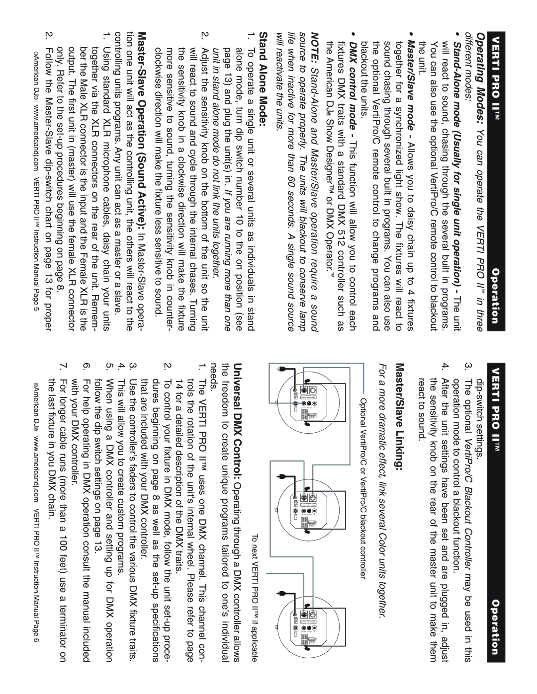
Master/Slave Linking:
For a more dramatic effect, link several Color units together.
Optional VertiPro/C or VertiPro/C blackout controller
1 = | 1 = | 1 = |
Grand 2 = | Grand 2 = | Grand 2 = |
Data - | Data - | Data - |
3 = | 3 = | 3 = |
Data + | Data + | Data + |
To next VERTI PRO II™ if applicable
Universal DMX Control: Operating through a DMX controller allows the freedom to create unique programs tailored to one’s individual needs.
1.The VERTI PRO II™ uses one DMX channel. This channel con- trols the rotation of the unit’s internal wheel. Please refer to page 14 for a detailed description of the DMX traits.
2.To control your fixture in DMX mode, follow the unit
3.Use the controller’s faders to control the various DMX fixture traits.
4.This will allow you to create custom programs.
5.When using a DMX controller and setting up for DMX operation follow the dip switch settings on page 13.
6.For help operating in DMX operation consult the manual included with your DMX controller.
7.For longer cable runs (more than a 100 feet) use a terminator on
the last fixture in you DMX chain.
©American DJ® www.americandj.com VERTI PRO II™ Instruction Manual Page 5 | ©American DJ® www.americandj.com VERTI PRO II™ Instruction Manual Page 6 |